
Frequency diversity array synthetic aperture three-dimensional imaging radar system and imaging method thereof

A frequency diversity array and three-dimensional imaging technology, which is applied to radio wave measurement systems, instruments, and measurement devices, can solve problems such as difficult implementation, complex imaging algorithms, and complex synthetic aperture radar transmission systems, and achieve simple forms, lower requirements, and Cost and the effect of saving the number of radars

Active Publication Date: 2019-07-12
GUILIN UNIV OF ELECTRONIC TECH
View PDF9 Cites 12 Cited by
  • Summary
  • Abstract
  • Description
  • Claims
  • Application Information

AI Technical Summary

Problems solved by technology

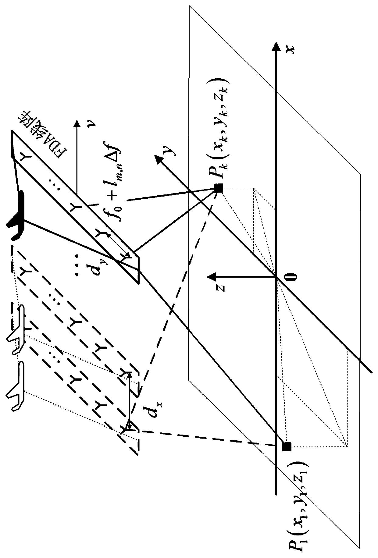
[0006] The technical problem to be solved by the present invention is that the two-dimensional planar frequency diversity array is not easy to be used in actual scenes and is difficult to realize, the traditional linear array synthetic aperture radar transmission system is complicated, and the traditional three-dimensional synthetic aperture radar imaging algorithm is complicated. Provide a frequency diversity array synthetic aperture three-dimensional imaging radar system and its target three-dimensional imaging method, the purpose is to realize multi-target three-dimensional imaging

Method used


Image

  • Frequency diversity array synthetic aperture three-dimensional imaging radar system and imaging method thereof
  • Frequency diversity array synthetic aperture three-dimensional imaging radar system and imaging method thereof
  • Frequency diversity array synthetic aperture three-dimensional imaging radar system and imaging method thereof

Examples


Embodiment Construction

[0059] The content of the present invention will be further described below in conjunction with the embodiments and the accompanying drawings, but the present invention is not limited thereto.

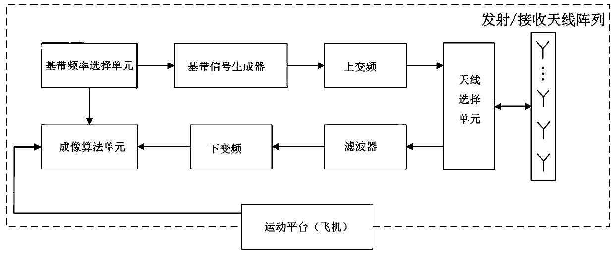
[0060] refer to Figure 1-2 , frequency diversity array synthetic aperture three-dimensional imaging radar system of the present invention, by 1 linear frequency diversity array radar ( figure 1 middle rectangle solid line area) and motion platform. The motion platform in the present invention is an airplane, and the linear frequency diversity array radar is mounted on the airplane.

[0061] The linear frequency diversity array radar includes a transmitting part and a receiving part;

[0062] The transmitting part includes a baseband frequency selection unit, a baseband signal generator, an up-conversion unit, an antenna selection unit and a transmitting antenna array connected in sequence;

[0063] The receiving part includes a receiving antenna array, an antenna selection unit, a ...


PUM


Abstract

The invention discloses a frequency diversity array synthetic aperture three-dimensional imaging radar system and an imaging method thereof. The system is composed of a linear frequency diversity array radar and a motion platform (airplane). The array radar comprises a transmitting part and a receiving part, wherein the transmitting part comprises a baseband frequency selection unit, a baseband signal generator, an up-converter, an antenna selection unit and a transmitting antenna array which are sequentially connected; the receiving part comprises a receiving antenna array, an antenna selection unit, a filter and a down-conversion and imaging algorithm unit which are sequentially connected; a linear frequency diversity array radar is installed on the motion platform, and the motion platform is connected with an imaging algorithm unit of the linear frequency diversity array radar. Under the condition that a frequency diversity array is used by the system, aperture synthesis is combinedto complete target three-dimensional imaging. The imaging method is simple in transmitted signal form, the distance direction resolution can be obtained without pulse compression, and the distance direction image, the azimuth direction image and the pitching direction image of the target can be obtained at the same time through one-time phase compensation.

Description

technical field [0001] The invention relates to the technical field of radar signal processing, in particular to a frequency diversity array synthetic aperture three-dimensional imaging radar system and an imaging method thereof. Background technique [0002] Three-dimensional synthetic aperture radar (Three-dimensional Synthetic Aperture Radar, 3D-SAR) introduces linear array antennas in the vertical direction of the flight plane to form a real aperture, thus possessing three-dimensional resolution capabilities in the range direction, azimuth direction and vertical direction. The imaging process is based on the traditional two-dimensional SAR imaging principle, using pulse compression technology to obtain high resolution in the range direction, using the synthetic aperture principle to obtain high resolution in the azimuth direction, and using the real aperture to obtain high resolution in the vertical direction. However, in terms of system implementation, due to the need t...

Claims


Application Information

Patent Timeline
IPC IPC(8): G01S13/90
Inventor 廖可非李晶晶欧阳缮廖桂生蒋俊正杜毅
Owner GUILIN UNIV OF ELECTRONIC TECH
Learn More