Light bar bending resistance testing machine

A technology of bending resistance and testing machine, which is applied in the direction of lamp testing, measuring electricity, and using stable tension/pressure to test the strength of materials, etc. It can solve the problem that it is difficult to accurately test and evaluate the bending resistance of light bars and cannot be effective Assess the bending resistance of the light bar and the inability to scientifically evaluate the reliability of the light bar, etc., to achieve accurate testing and evaluation of the bending resistance, improve scientific accuracy, and avoid instability

Pending Publication Date: 2019-07-12
HUIZHOU WISVA OPTOELECTRONICS CO LTD
View PDF0 Cites 1 Cited by
  • Summary
  • Abstract
  • Description
  • Claims
  • Application Information

AI Technical Summary

Problems solved by technology

[0004] The purpose of the present invention is to provide a light bar bending resistance testing machine to solve the problem that the method for testing the bending resistance of LED light bars in the market proposed by the above-mentioned background technology is difficult to accurately test because of different testers and different speeds. And to evaluate the bending resistance of the light bar, it is impossible to scientifically evaluate the reliability of the light bar, without professional equipment, relying on manual bending of the light bar, without long-term and precise angle control, the test results have a great human influence, The efficiency is very low, and it is impossible to effectively evaluate the bending resistance of the light bar

Method used


Image

  • Light bar bending resistance testing machine
  • Light bar bending resistance testing machine
  • Light bar bending resistance testing machine

Examples


Embodiment Construction

[0023] The following will clearly and completely describe the technical solutions in the embodiments of the present invention with reference to the accompanying drawings in the embodiments of the present invention. Obviously, the described embodiments are only some, not all, embodiments of the present invention. Based on the embodiments of the present invention, all other embodiments obtained by persons of ordinary skill in the art without making creative efforts belong to the protection scope of the present invention.

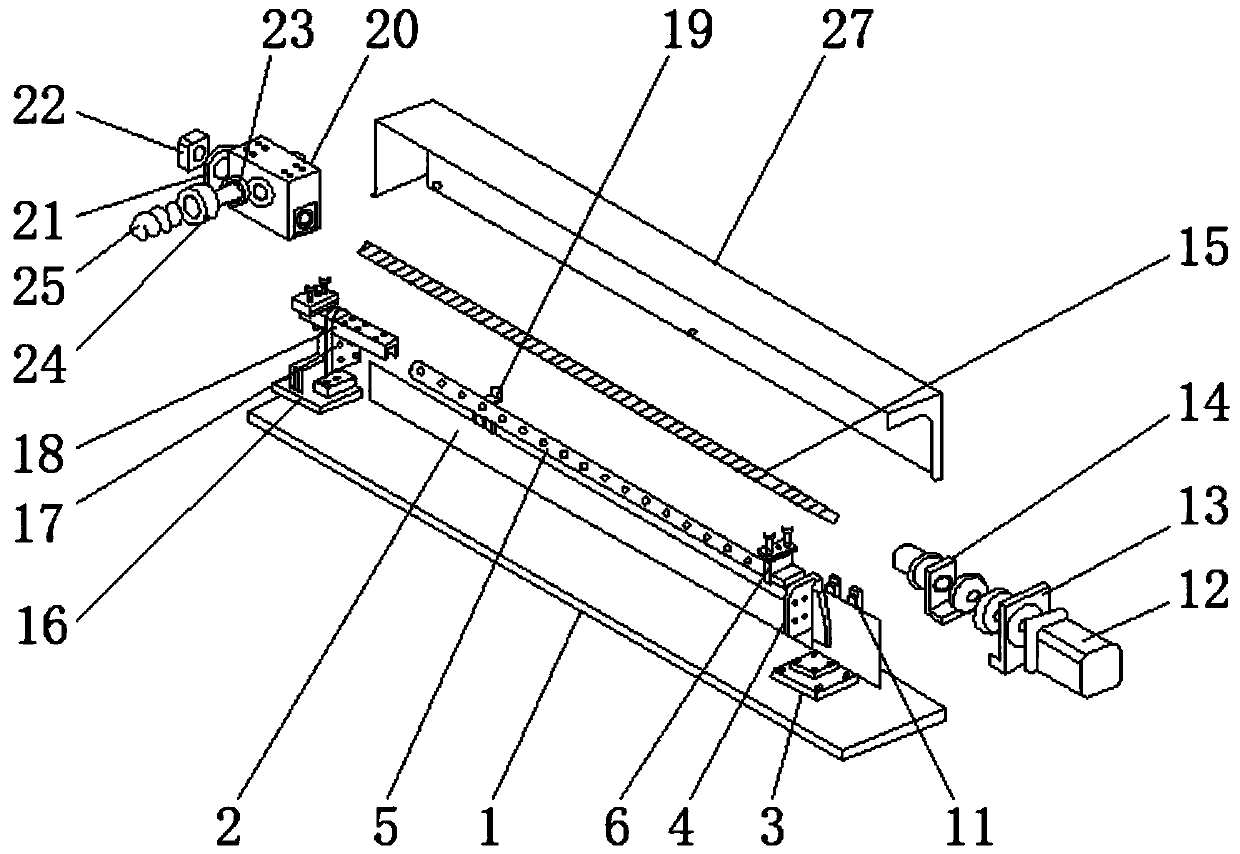
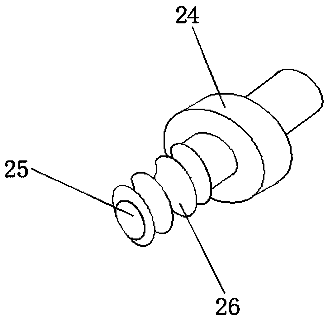
[0024] see Figure 1-3 , the present invention provides a technical solution: a light bar bending resistance test machine, including a general assembly base plate 1, a protective baffle plate 2, a fixed end base plate 3, a fixed end vertical plate 4, a linear guide rail 5, and a fixed seat bracket 6 , fixed seat 7, insulating silicone skin 8, fixed screw hole 9, wing nut 10, photoelectric sensor 11, motor 12, motor seat 13, fixed end support 14, screw rod 15, ...


PUM

PropertyMeasurementUnit
diameteraaaaaaaaaa

Abstract

The invention discloses a light bar bending resistance testing machine. The light bar bending resistance testing machine comprises a general assembly bottom plate, a motor base, an adjusting end bottom plate and an action block, wherein a linear guide rail is arranged on the surface of the general assembly bottom plate, a lead screw is arranged at the upper portion of the linear guide rail, a protective baffle is arranged at the side surface of the general assembly bottom plate, a fixed seat is arranged on the surface of a fixed seat support table, butterfly nuts are connected at the internalportions of fixed screw holes, a motor is arranged on one side of the motor base, and one end of the lead screw penetrates through a fixed end support piece and then is connected with the motor; the surface of an adjusting end vertical plate is provided with a guide rail sliding block, the outer side of a poke rod is connected with a roller, and the surface of the roller is provided with guide slots. The light bar bending resistance testing machine is provided with the motor, the lead screw and the action block, and the motor and the thread transmission mode allow the roller to move at a constant speed so as to solve the stability of dragging for a long time, avoid the instability of manual operation and the fatigability of long-time operation and improve the efficiency of test work.

Description

technical field [0001] The invention relates to the technical field of light bar testing machines, in particular to a light bar bending resistance testing machine. Background technique [0002] The rapid development of LED light strips improves the lighting effect and reduces the energy loss of traditional light bulbs. In order to improve the quality of LED light strips, it is necessary to test the bending resistance of LED light strips. At present, there is no one in the industry. Equipment that can test the bending performance of LED flexible light strips. The bending performance of light strips in the industry is tested by using a round tube with a diameter of 40-50mm, wrapping a light strip around it, and pulling it back and forth. To test the reliability of original components such as light strips and lamp beads and FPC circuits. [0003] At present, the methods for testing the bending resistance of LED light strips in the market will be difficult to accurately test an...

Claims


Application Information

Patent Timeline
Patent Type & Authority Applications(China)
IPC IPC(8): G01R31/44G01R1/02G01N3/02G01N3/08
CPCG01N3/02G01N3/08G01R1/02G01R31/44
Inventor 徐姗
Owner HUIZHOU WISVA OPTOELECTRONICS CO LTD
Why Eureka
Try Eureka