Printed circuit board component testing device

A printed circuit board and component testing technology, applied in printed circuit testing, electronic circuit testing, measuring devices, etc., can solve problems such as large elasticity, affecting test accuracy and reliability, and inconvenient testing of PCB components, so as to improve test efficiency, Stable test results and improved convenience

Pending Publication Date: 2019-07-12
MICROPORT SORIN CRMSHANGHAICO LTD
View PDF0 Cites 8 Cited by
  • Summary
  • Abstract
  • Description
  • Claims
  • Application Information

AI Technical Summary

Problems solved by technology

[0004] 1. Complex structure, large volume and inconvenient use
[0005] 2. For cardiac pacemakers, the program control head of the program control instrument usually used to test the above PCB components cannot be close to the PCB component to be tested, so it cannot establish a short-distance communication connection with the PCB component to be tested, so the program control instrument Inconvenient testing of PCB components
[0006] 3. The signal transmission lines 1071 and 1072 are both very long. For PCB component testing of electronic products with weak signals such as pacemakers without leads, the noise in the test environment is likely to interfere with the test signal through the signal transmission lines 1071 and 1072, affecting the test accuracy. and reliability
[0007] 4. The test probes 1061 set on the top surface of the support base 104 have a relatively large pin-point spacing, which cannot meet the requirements of PCB component testing for multi-test point and micro-pitch products.
[0008] 5. The elastic force of the test probe 1062, the balance bar 105 and other structures is relatively large, and it is easy to cause damage such as bending and dark cracks to the micro PCB components during the test

Method used


Image

  • Printed circuit board component testing device
  • Printed circuit board component testing device
  • Printed circuit board component testing device

Examples


Embodiment Construction

[0039] In order to make the purpose and features of the present invention more obvious and understandable, the technical solutions of the present invention will be described in detail below in conjunction with the accompanying drawings. However, the present invention can be implemented in different forms and should not be limited to the described embodiments. It should be noted that the drawings are all in a very simplified form and use imprecise ratios, which are only used to facilitate and clearly assist the purpose of illustrating the embodiments of the present invention.

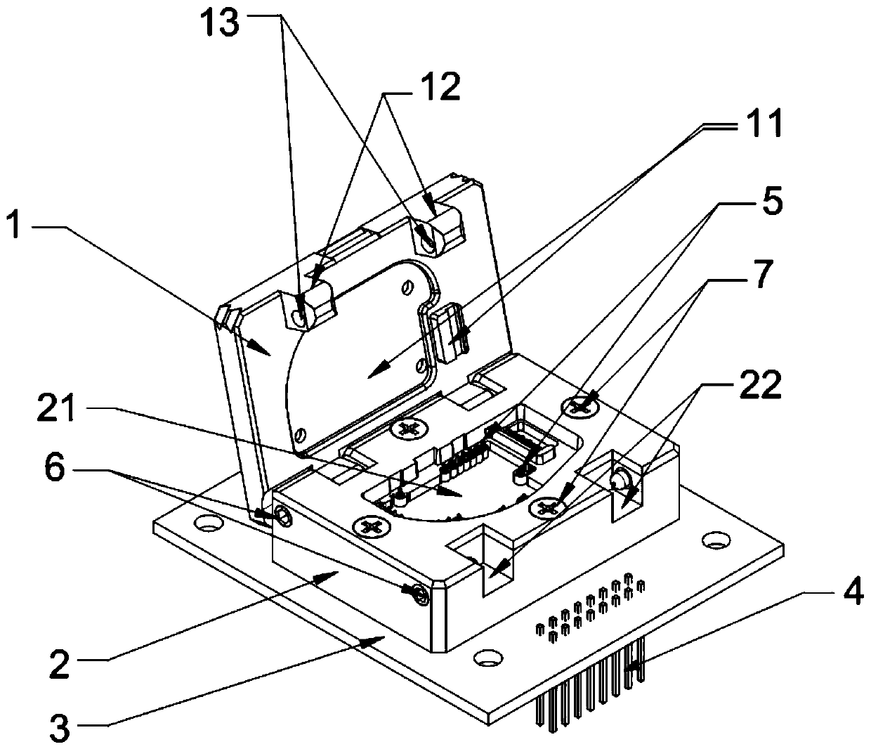
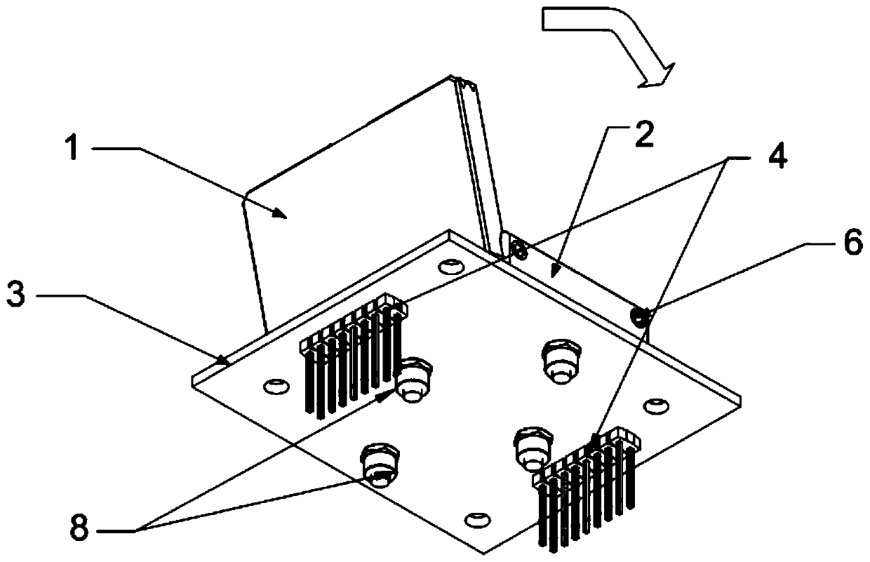
[0040] Please refer to Figure 2 to Figure 4 , an embodiment of the present invention provides a printed circuit board assembly testing device, including a cover 1 , a circuit board fixing base 2 , a carrier board 3 and a connector 4 which are sequentially fitted from top to bottom.

[0041] The connector 4 can be fixedly arranged on the side of the carrier board 3 facing away from the circuit board fixi...


PUM


Abstract

The invention provides a printed circuit board component testing device. The device is mainly composed of a cover and a circuit board fixing base, wherein the cover can be buckled to the circuit boardfixing base through a connecting mechanism, and therefore a printed circuit board component can be safely and reliably placed in a fixing slot of the circuit board fixing base and make contact with atest probe. According to the testing device, the arrangement of a balancing rod is canceled, the structure is simple, the size is small, and in the testing process of the printed circuit board component, the test result can be stable.

Description

technical field [0001] The invention relates to the technical field of circuit board assembly testing, in particular to a printed circuit board assembly testing device suitable for active products such as implanted / interventional medical devices. Background technique [0002] As active products such as implantable / interventional medical devices continue to be miniaturized and miniaturized, more stringent design requirements are imposed on the volume of printed circuit board (PCB) components of these active products. At the same time, implantable / interventional medical devices have extremely high requirements on the safety and effectiveness of products. How to conduct comprehensive and effective testing of PCB components with complex functions and small volumes is a key point in the entire design, development and production process. Therefore, there is an urgent need for a high-efficiency and reliable PCB assembly testing device. [0003] figure 1 Shown is a schematic struc...

Claims


Application Information

Patent Timeline
Patent Type & Authority Applications(China)
IPC IPC(8): G01R31/28G01R1/04
CPCG01R31/2806G01R31/2808
Inventor 程灿邱丰伟姜震宇
Owner MICROPORT SORIN CRMSHANGHAICO LTD
Why Eureka
Try Eureka