
New-old road overlap joint reflective crack construction machinery and pavement construction method

A technology of reflective cracks and construction machinery, applied in the field of engineering construction, can solve problems such as low construction efficiency, road damage, reflective cracks on the road surface, etc., and achieve the effect of improving construction efficiency

Pending Publication Date: 2019-07-12
ANHUI KAIYUAN HIGHWAY & BRIDGE +1
View PDF12 Cites 6 Cited by
  • Summary
  • Abstract
  • Description
  • Claims
  • Application Information

AI Technical Summary

Problems solved by technology

However, cement-stabilized gravel is used as the base material, and the disadvantage is that it is prone to dry shrinkage and temperature shrinkage cracks, which will aggravate along with the road's entire service life and increase with the age of the road, thereby causing reflective cracks on the road surface
[0003] In road maintenance projects, concrete is often used to fill the milled potholes at the cracks, but the joint between the new and old pavement bases after filling forms a seam, which is easy to cause reflective cracks on the road surface, resulting in repair The road at the end was destroyed again, and the above-mentioned cracks were cut with a hand-push seam cutting machine to cut the road surface at the cracks for filling seams. The type seam cutting machine needs to open two seams, and then it needs to use a breaker to break the roadbed between the two seams, and finally use manual or excavating equipment to excavate the broken roadbed to realize the new construction. The construction at the junction of the old road surface, the above-mentioned construction efficiency is low

Method used


Image

  • New-old road overlap joint reflective crack construction machinery and pavement construction method
  • New-old road overlap joint reflective crack construction machinery and pavement construction method
  • New-old road overlap joint reflective crack construction machinery and pavement construction method

Examples


Embodiment Construction

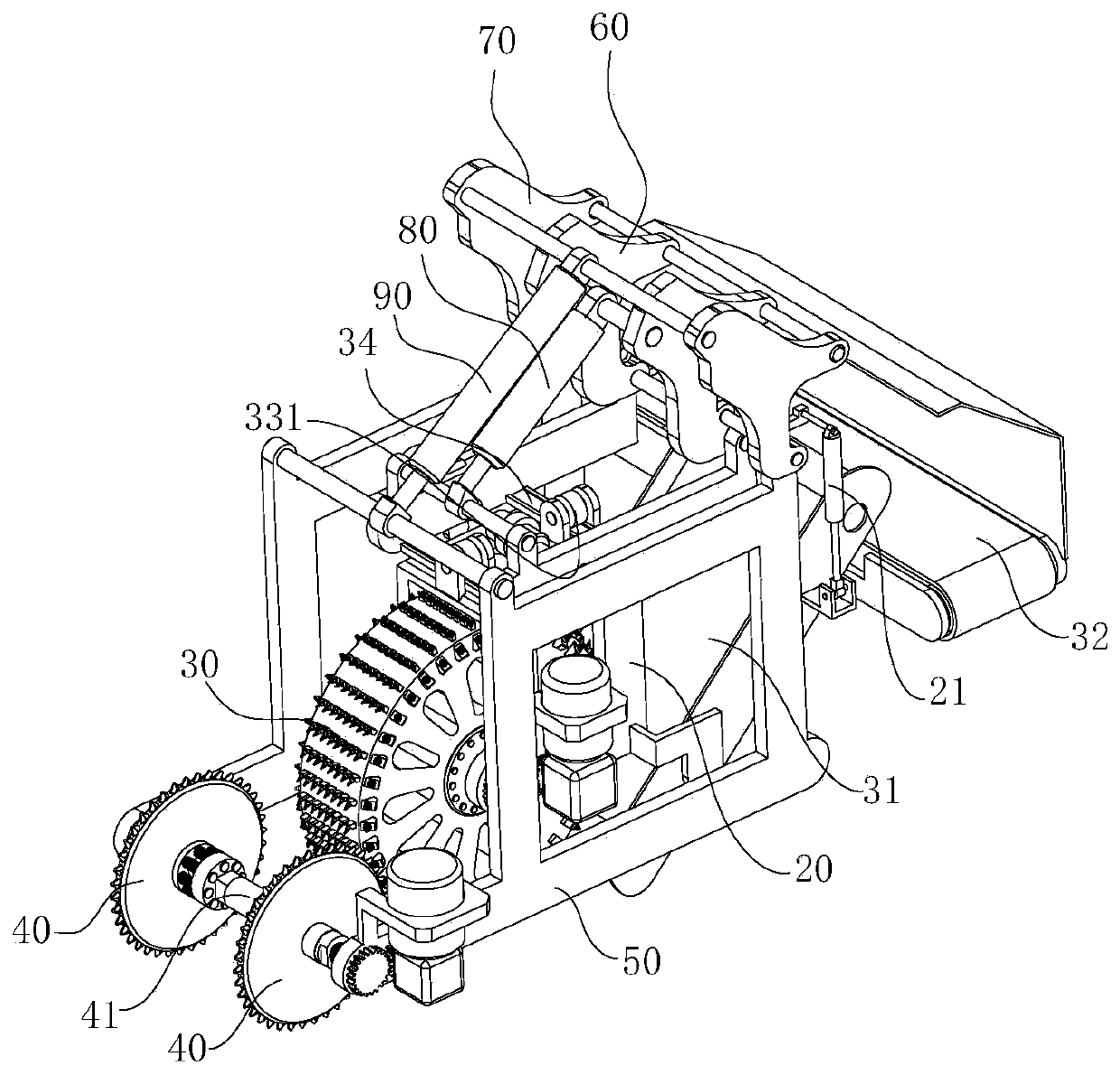
[0028] refer to Figure 1 to Figure 10 , the structural characteristics of the new and old road lap reflective crack construction machinery are described in detail as follows:

[0029] New and old road overlap reflective crack construction machinery, including a bracket arm 20 arranged on a mobile vehicle 10, a milling wheel 30 is rotatably arranged on the bracket arm 20, and the milling wheel 30 has a wheel core and is connected to a driving mechanism , the driving mechanism drives the milling wheel 30 to rotate, and the two sides in front of the milling wheel 30 are provided with cutting disc cutters 40, the disc core of the cutting disc cutter 40 is horizontal and connected with the power mechanism, and the power mechanism drives the cutting disc cutter 40 to rotate;

[0030] combine figure 1 As shown, during the moving process of the moving vehicle 10 supporting the cutting disc cutter 40, the power mechanism drives the cutting disc cutter 40 to rotate, thereby realizing ...


PUM


Abstract

The invention relates to new-old road overlap joint reflective crack construction machinery. The new-old road overlap joint reflective crack construction machinery comprises a bracket arm arranged ona moving vehicle, the bracket arm is rotatably provided with a milling wheel, a wheel core of the milling wheel is horizontally arranged and connected with a drive mechanism, the drive mechanism drives the milling wheel to rotate, cutting disc cutters are arranged on the two sides of the front of the milling wheel, disc cores of the cutting disc cutters are horizontally arranged and connected witha power mechanism, the power mechanism drives the cutting disc cutters to rotate, in the process of the moving vehicle supporting and sending the cutting disc cutters to move, the power mechanism drives the cutting disc cutters to rotate, thus joint cutting operation is achieved, the drive mechanism drives the milling wheel to rotate, thus excavation operation of pavement between two cracks is achieved, after joint cutting is completed by the cutting disc cutters, a crack groove used for overlapping of a new pavement and an old pavement can be formed, and thus the construction efficiency canbe effectively improved through the construction machinery.

Description

technical field [0001] The invention relates to the field of engineering construction, in particular to a construction machine for lapping reflective cracks between old and new roads and a road surface construction method. Background technique [0002] In road construction projects, semi-rigid materials are mostly used as base materials, among which cement-stabilized gravel has high strength and good water stability, and is widely used in road construction. However, cement-stabilized gravel is used as the base material. The disadvantage is that it is prone to dry shrinkage and temperature shrinkage cracks, which accompany the entire service life of the road and aggravate with the increase of road age, thereby causing reflective cracks on the road surface. [0003] In road maintenance projects, concrete is often used to fill the milled potholes at the cracks, but the joint between the new and old pavement bases after filling forms a seam, which is easy to cause reflective cra...

Claims


Application Information

Patent Timeline
Patent Type & Authority Applications(China)
IPC IPC(8): E01C23/09E01C23/088
CPCE01C23/0933E01C23/088
Inventor 黄会彬章和敏马彦唐世棚朱忠林张涛
Owner ANHUI KAIYUAN HIGHWAY & BRIDGE
Learn More