Separated lockstitch sewing device and sewing method

A separate, stitch technology, applied in the field of stitching, can solve the problems of small end size, inability to stitch three-dimensionally, and long length, etc., and achieve the effects of controllable spacing, controllable sewing thread tension, and stable stitching quality.

Active Publication Date: 2019-07-12
AEROSPACE RES INST OF MATERIAL & PROCESSING TECH +1
View PDF8 Cites 3 Cited by
  • Summary
  • Abstract
  • Description
  • Claims
  • Application Information

AI Technical Summary

Problems solved by technology

Because the radiator is a closed structure, and has the characteristics of large length along the direction of the busbar (up to 1.5m) and small size of the small end (up to 60mm), the existing commercial sewing machines cannot realize three-dimensional sewing in the direction of the busbar on the tapered tooling

Method used


Image

  • Separated lockstitch sewing device and sewing method
  • Separated lockstitch sewing device and sewing method
  • Separated lockstitch sewing device and sewing method

Examples


Embodiment Construction

[0030] Exemplary embodiments of the present disclosure will be described in more detail below with reference to the accompanying drawings. Although exemplary embodiments of the present disclosure are shown in the drawings, it should be understood that the present disclosure may be embodied in various forms and should not be limited by the embodiments set forth herein. Rather, these embodiments are provided for more thorough understanding of the present disclosure and to fully convey the scope of the present disclosure to those skilled in the art. It should be noted that, in the case of no conflict, the embodiments of the present invention and the features in the embodiments can be combined with each other. The present invention will be described in detail below with reference to the accompanying drawings and examples.

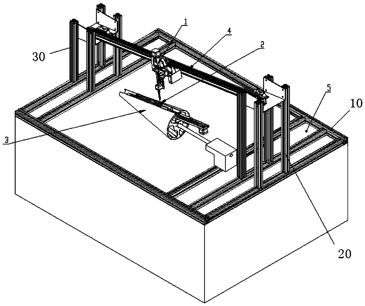
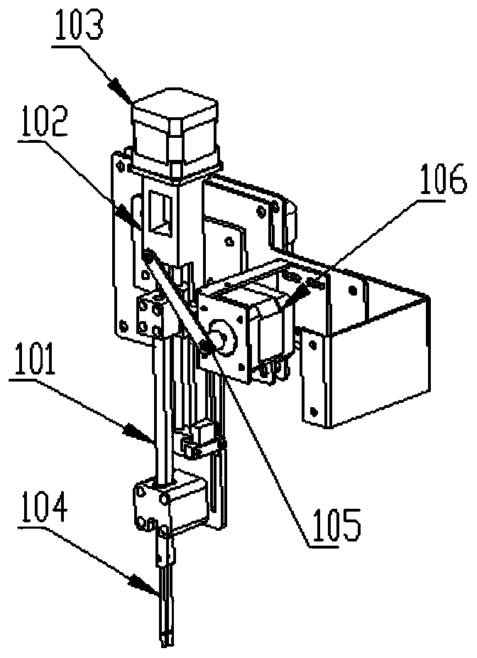
[0031] see figure 1 , the embodiment of the present invention provides a separate lockstitch sewing device, which includes a split head assembly and a shuttl...


PUM


Abstract

The invention belongs to the technical field of sewing and discloses a separated lockstitch sewing device and sewing method. By split arrangement of a machine head component and a shuttle box component, in sewing, the machine head component is suspended above a to-be-sewn material through a first slide rail, a shuttle unit is arranged below the to-be-sewn material through a second slide rail, anda needle unit and the shuttle unit are controlled to synchronously move along a to-be-sewn portion to realize lockstitch sewing of sewing points in sequence. By adoption of the method, mechanical sewing of a conical structure with generatrix direction length greater than 1.5m and small end size less than 60mm is realized, staggering, slipping and creasing of thin-film material layers of a conicalmultilayer flexible thin film composite product are avoided, and sewing efficiency is improved. In addition, stitch pitch controllability, sewing thread tension controllability and sewing quality stability are realized, and the method is suitable for batch production.

Description

technical field [0001] The invention relates to a separate lock stitch sewing device and a sewing method, belonging to the technical field of sewing. Background technique [0002] The radiator is usually used for radar stealth, its shape matches the outer surface of the stealth target, and it is set outside the stealth target. The commonly used radiator is usually a cone-shaped cylindrical structure. In order to better realize the stealth function of absorbing waves, the radiator is formed by laminating multiple layers of materials. [0003] At present, usually according to the design structure, the multi-layer material is cut into two fan-shaped structures of the same size, and the two fan-shaped structures are surrounded and sewn together to form a cone-shaped radiator. Since the thickness of the fan-shaped structure is about 1-2mm, the maximum difference in the arc length of the uppermost layer and the lowermost layer of the laminated material (fan-shaped) is greater tha...

Claims


Application Information

Patent Timeline
IPC IPC(8): D05B1/12D05B49/00D05B57/16D05B57/38D05B69/10
CPCD05B1/12D05B49/00D05B57/16D05B57/38D05B69/10
Inventor 陈风波李凡魏赛王小黎丁浩亮
Owner AEROSPACE RES INST OF MATERIAL & PROCESSING TECH
Why Eureka
Try Eureka