A submersible retractable device

A technology for submersibles and retractable mechanisms, which is applied in the directions of transportation and packaging, ships, and special-purpose vessels, etc. Joint submersible retraction and other issues, to achieve the effect of high degree of automation, convenient and reliable use, easy retraction

Inactive Publication Date: 2020-11-06
TIANJIN UNIV
View PDF1 Cites 1 Cited by
  • Summary
  • Abstract
  • Description
  • Claims
  • Application Information

AI Technical Summary

Problems solved by technology

Especially when it comes to multi-joint submersibles, such as the patent (Patent No.: CN106744258A) of "A Structure-Adjustable Submersible Suspension-type Recovering Device and Method" (Patent No.: CN106744258A) adopts a cage-type recovery device, which is easy for multi-joint The sensors on the surface of the submersible cause damage, which can easily damage the submersible
For example, the patent "deployment and recovery device for autonomous underwater vehicles" (patent number: 202379064U) has only two sets of grasping arms, which cannot satisfy the recovery and deployment of multi-joint submersibles
[0004] The existing working device can no longer satisfy the retraction and deployment of the multi-joint submersible. At the same time, in order to improve the working efficiency and safety of the deep-sea retraction of the submersible, prevent the submersible from violent swings during the retraction process, and avoid the submersible from being hit, Need more advanced submersible retractable device and control method

Method used


Image

  • A submersible retractable device
  • A submersible retractable device
  • A submersible retractable device

Examples


Embodiment Construction

[0035] The present invention will be further described in detail below in conjunction with the drawings and specific implementation process.

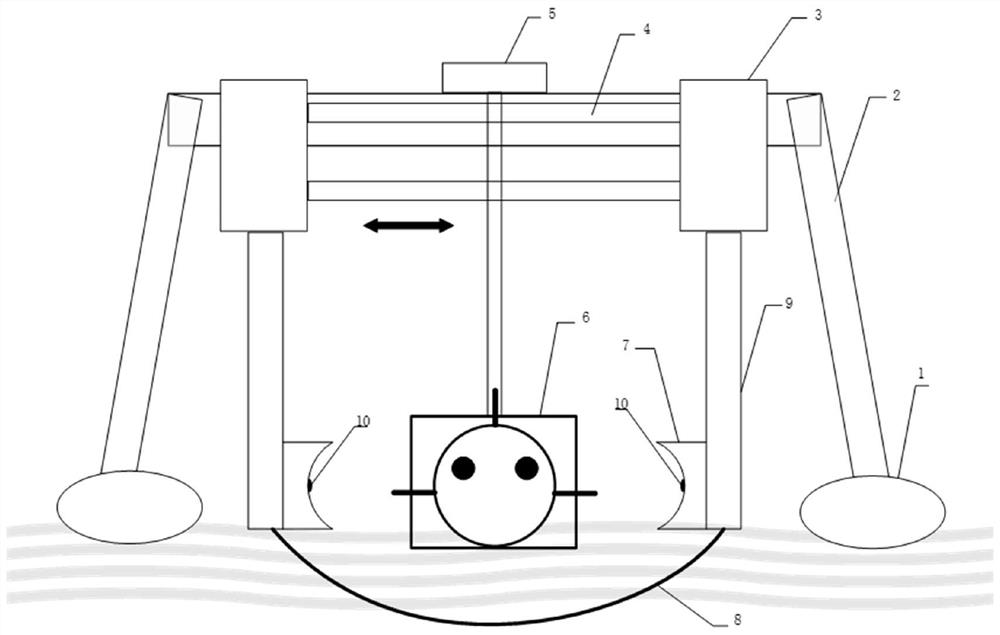
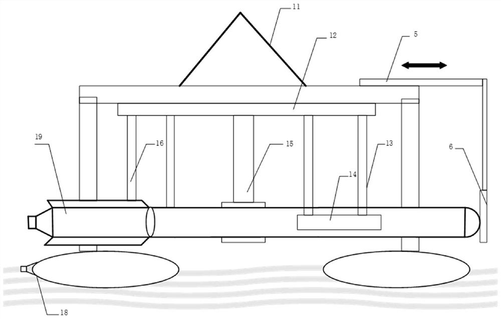
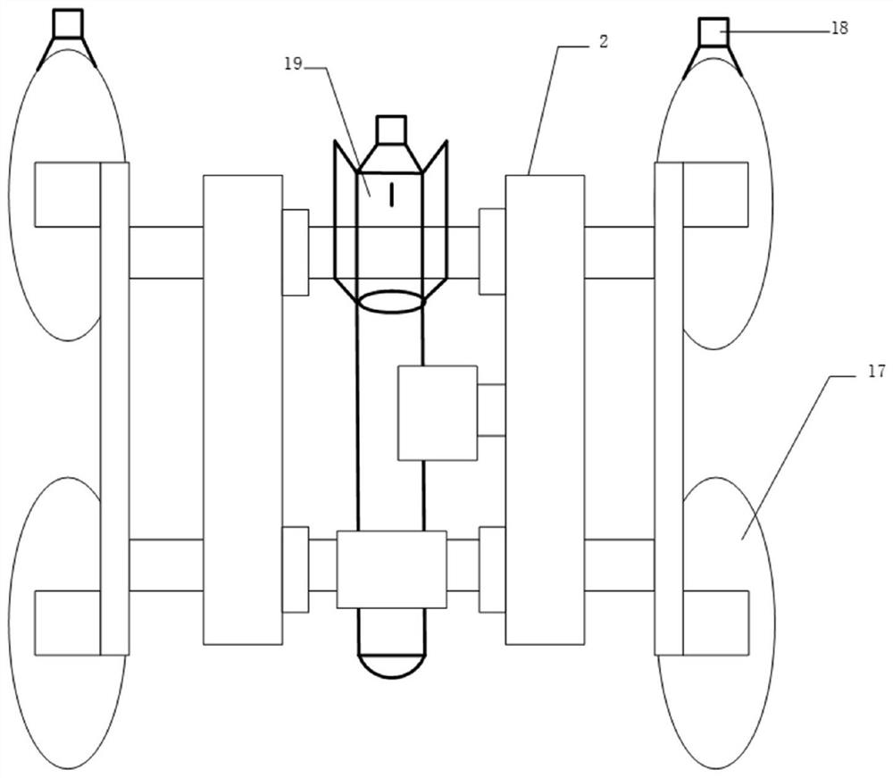
[0036] Such as figure 1 A submersible vehicle retracting device is shown for recovering and deploying torpedo-shaped submersible vehicle 20. It is composed of a control unit, a pressure sensor 10, a power supply unit, an electric drive unit, a remote control, and a retractable mechanism. among them,

[0037] The retracting mechanism includes a buoyancy base 1, a door-shaped bracket 2, a telescopic platform 3, an extension arm 5, a limit device 6, a grab arm 9, etc. The door-shaped bracket 2 is fixedly connected to the buoyancy base 1, and two horizontal Guide rail 4, the telescopic platform is mounted on two horizontal guide rails 4, three pairs of grab arms 9 are arranged below the telescopic platform, and a horizontal guide rail is arranged above the telescopic platform 3, which is connected to the extension arm 5 to achieve front-to-back...


PUM


Abstract

The invention relates to a submersible vehicle retraction device. The submersible vehicle retraction device comprises a control unit, a pressure sensor, a power supply unit, an electric drive unit anda retraction mechanism, wherein the retraction mechanism comprises a buoyancy base, a door-type bracket, a telescopic platform, an extension arm and a plurality of grasping arms. The buoyancy base comprises at least one buoyancy block and at least one hydraulic propeller, wherein the hydraulic propellers are connected with the buoyancy block. A bracket is fixedly connected to the upper part of the buoyancy base, a horizontal guide rail is arranged above the bracket, the upper part of the telescopic platform is arranged on two horizontal guide rails, and the telescopic platform can move alongwith the horizontal guide rails, and the grasping arms are connected to the lower part of the telescopic platform. The tail end of each grasping arm is fixedly connected with contact plates for clamping a submersible vehicle from different directions through the contact plates, and the grasping arms are driven by a servo motor to realize contraction and expansion movement under the action of a control unit. The pressure sensor is arranged at the contact surface of the grasping arms and the submersible vehicle and is used for measuring a pressure value between the grasping arm contact plates and the submersible vehicle and sending the pressure value to the control unit.

Description

Technical field [0001] The invention belongs to the technical field of water surface deployment and recovery of underwater vehicles. Background technique [0002] The submersible is an active deep diving device with underwater observation and operation capabilities. It is mainly used to perform tasks such as underwater survey, seabed exploration, and seabed development. In the business process of submersible vehicles, deployment and recovery operations are extremely important links, especially the recovery link, which is directly related to the availability of underwater unmanned vehicles. [0003] Most of the deployment and recovery of submersibles are directly hoisted based on mother ship cranes or A-frames. Due to the high wind and waves in offshore operations, the submersible oscillates with the waves on the surface of the water, which is dangerous for the personnel operating in the water and is inconvenient and efficient. At the same time, the structure of the submersible i...

Claims


Application Information

Patent Timeline
Patent Type & Authority Patents(China)
IPC IPC(8): B63G8/00
CPCB63G8/001B63G2008/005
Inventor 刘迎澍赵士环孟庆浩任超
Owner TIANJIN UNIV
Why Eureka
Try Eureka