
Method, device and equipment for checking azimuth angle of base station and medium

An azimuth and base station technology, applied in the field of base station azimuth angle verification, can solve the problems of insufficient intelligence, insufficient precision and efficiency, and low accuracy of natural verification results, and achieve the effect of solving intelligence and improving efficiency.

Active Publication Date: 2019-07-09
XIANGYANG BRANCH CHINA MOBILE GRP HUBEI CO LTD +1
View PDF7 Cites 2 Cited by
  • Summary
  • Abstract
  • Description
  • Claims
  • Application Information

AI Technical Summary

Problems solved by technology

[0003] However, the logical rule verification method can only be limited to the logical problems of the existing network parameters, and cannot verify a large number of base stations that do not have logical problems; the drive test sampling points are generally distributed in urban grids and on ATU roads. What is obtained is a summary of the drive test behavior of an end user. The selection of sampling points is not extensive and objective, and the log test chart needs to be uploaded manually. Naturally, the accuracy of the verification results is not high.
Existing verification methods for abnormal parameters have the limitations of insufficient intelligence, precision and low efficiency, and the implementation of verification work often brings a series of operating costs such as the purchase and loss of tower workers, vehicles and instruments

Method used


Image

  • Method, device and equipment for checking azimuth angle of base station and medium
  • Method, device and equipment for checking azimuth angle of base station and medium
  • Method, device and equipment for checking azimuth angle of base station and medium

Examples


Embodiment Construction

[0046] The characteristics and exemplary embodiments of various aspects of the present invention will be described in detail below. In order to make the purpose, technical solutions and advantages of the present invention clearer, the present invention will be further described in detail below in conjunction with the accompanying drawings and embodiments. It should be understood that the specific embodiments described here are only configured to explain the present invention, not to limit the present invention. It will be apparent to one skilled in the art that the present invention may be practiced without some of these specific details. The following description of the embodiments is only to provide a better understanding of the present invention by showing examples of the present invention.

[0047] It should be noted that in this article, relational terms such as first and second are only used to distinguish one entity or operation from another entity or operation, and do ...


PUM


Abstract

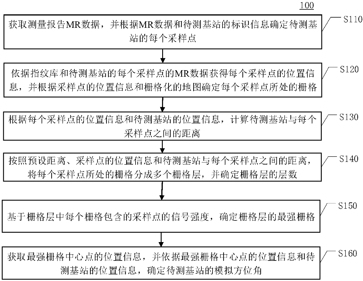
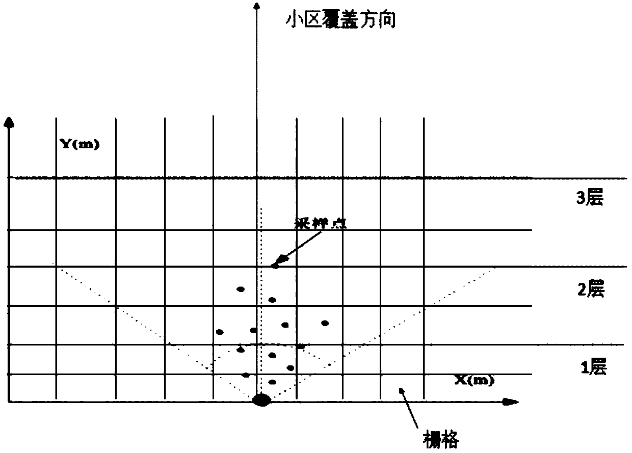
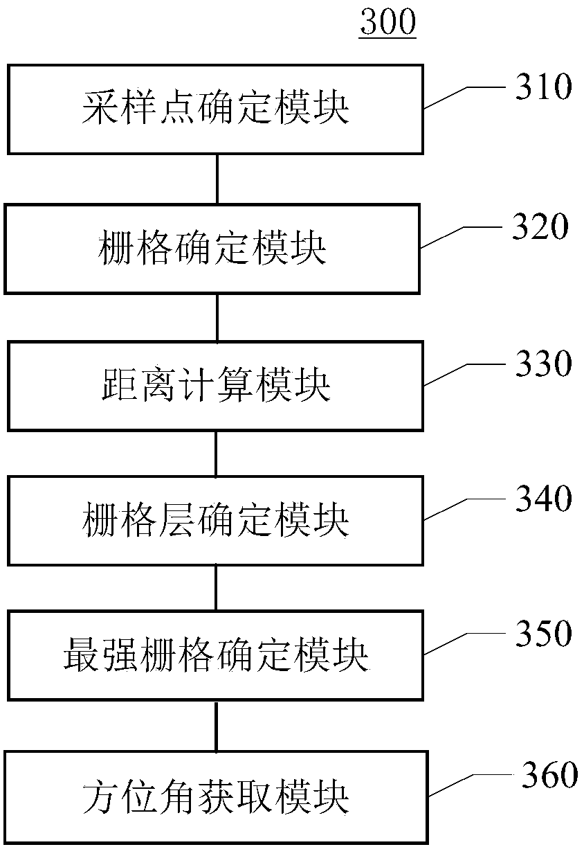
The invention discloses a method, a device and equipment for checking an azimuth angle of a base station and a medium. The method comprises the following steps: acquiring MR data of a measurement report, determining each sampling point of a to-be-measured base station; obtaining position information of each sampling point, determining a grid where each sampling point is located according to the position information of the sampling point and the rasterized map; calculating the distance between the base station to be measured and each sampling point; dividing the grid where each sampling point is located into a plurality of grid layers, determining the number of layers of the grid layers; determining the strongest grid of the grid layer based on the signal intensity of the sampling point contained in each grid in the grid layer; acquiring position information of the strongest grid center point, and determining a simulation azimuth angle of the to-be-tested base station according to the position information of the strongest grid center point and the position information of the to-be-tested base station. According to the method, the device, the equipment and the medium for checking theazimuth angle of the base station provided by the embodiment of the invention, the abnormal base station checking efficiency is improved.

Description

technical field [0001] The present invention relates to the field of wireless technology, in particular to a method, device, equipment and medium for checking the azimuth angle of a base station. Background technique [0002] In network coverage optimization, the azimuth angle of the base station is a very important parameter. The azimuth angle of the base station determines the main coverage direction of the cell, but the azimuth angle of the base station may deteriorate due to various reasons. Existing implementation methods for abnormal work parameter verification are mainly carried out from two aspects: logical rules (the angle between any cell of the same base station with the same frequency is less than 60 degrees, etc.) and using drive test data to analyze theoretical azimuth and downtilt. [0003] However, the logical rule verification method can only be limited to the logical problems of the existing network parameters, and cannot verify a large number of base stati...

Claims


Application Information

Patent Timeline
IPC IPC(8): H04W4/021H04W24/08H04W24/10G01C1/00
CPCG01C1/00H04W4/021H04W24/08H04W24/10
Inventor 王颖刘宁张巧琳任达耀隋江雨章永崎李文华
Owner XIANGYANG BRANCH CHINA MOBILE GRP HUBEI CO LTD
Learn More