Transverse subtraction differential confocal ultra-long focal length measurement method

A technology of differential confocal and measurement methods, which is applied in geometrical characteristics/aberration measurement, optical performance testing, optical axis determination, etc. It can solve the problems of insufficient anti-environmental interference ability, low sensitivity of fixed focus, complex fixed focus system, etc. problems, to achieve the effect of improving anti-environmental interference ability, improving fixed-focus accuracy, and high-precision measurement

Active Publication Date: 2019-07-09
BEIJING INSTITUTE OF TECHNOLOGYGY
View PDF6 Cites 2 Cited by
  • Summary
  • Abstract
  • Description
  • Claims
  • Application Information

AI Technical Summary

Benefits of technology

This patented technology describes an improved technique for measuring long distance (LF), particularly by utilizing two different techniques: one involves capturing images from both sides of the object being measured while maintaining their original shape or size; another involves creating specific patterns on top of these captured image data to enhance its resolution capabilities during measurements. By combining these technologies together, this new approach allows for precise determination of LF values over longer distances than previously possible due to increased sensitiveness against distortion factors such as temperature fluctuation.

Problems solved by technology

This patented describes various techniques that aim towards improving precision measurements over longer distances called superfocal or short distance telescopics (STM). One solution involves utilizing these techniques together to increase the resolution and accuracy required for accurate long range measurement of microscope images.

Method used


Image

  • Transverse subtraction differential confocal ultra-long focal length measurement method
  • Transverse subtraction differential confocal ultra-long focal length measurement method
  • Transverse subtraction differential confocal ultra-long focal length measurement method

Examples


Embodiment

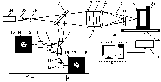
[0044] Such as Figure 5 As shown, this embodiment is based on the attached figure 1 The horizontal subtraction differential confocal ultra-long focal length measurement method, the measurement steps are:

[0045] a) Start the measurement software of the main control computer 30, turn on the laser 34, and the light emitted by the laser 34 passes through the microscope objective lens 35 and the pinhole 36 to form a point light source 1.

[0046] b) Adjust the plane reflector 6 so that it has the same optical axis as the reference lens 4 and the collimating lens 3, the light emitted by the point light source 1 passes through the beam splitter 2, the collimating lens 3 and the reference lens 4, and then converges into a measuring beam 5 to focus on On the apex of the plane mirror 6, the focused measurement beam 5 reflected by the apex of the plane mirror 6 passes through the reference lens 4 and the collimator lens 3, and then is reflected by the beam splitter 2 and enters the l...


PUM


Abstract

The invention discloses a transverse subtraction differential confocal ultra-long focal length measurement method and belongs to the technical field of optical precision measurement. In a confocal measurement system, the method comprises the following steps: firstly, in an airy disk image detected by a CCD, a large virtual pinhole detection area and a small virtual pinhole detection area are set through software, and two detected confocal characteristic curves are subjected to subtraction processing so as to sharpen the confocal characteristic curves, secondly, the sharpened confocal characteristic curves are subjected to differential motion subtraction processing so as to obtain an axial high-sensitivity differential confocal characteristic curve, then, when the differential confocal characteristic curve zero point and the focal point of the differential confocal measurement system are used to accurately correspond to the characteristics to measure the measured ultra-long focal length, high-precision fixed-focus addressing is carried out on the position of each vertex, and finally, the ultra-long focal length is accurately obtained through ray tracing compensation calculation, andhigh-precision measurement of the ultra-long focal length is achieved. The method has the advantages of being high in measurement precision, high in capability of environmental disturbance resistance, simple in structure and the like, and a wide application prospect is achieved in the technical field of optical precision measurement.

Description


Claims


Application Information

Patent Timeline
Owner BEIJING INSTITUTE OF TECHNOLOGYGY
Why Eureka
Try Eureka