Method for measuring bilateral dislocation differential confocal radius of curvature

A technology of differential confocal and radius of curvature, applied in measuring devices, instruments, optical devices, etc., can solve problems such as the difficulty of high-precision focusing, improve focus sensitivity and signal-to-noise ratio, and improve resistance to system aberrations , Improve the effect of anti-environmental interference ability

Active Publication Date: 2019-07-09
BEIJING INSTITUTE OF TECHNOLOGYGY
View PDF5 Cites 8 Cited by
  • Summary
  • Abstract
  • Description
  • Claims
  • Application Information

AI Technical Summary

Problems solved by technology

[0012] The purpose of the present invention is to solve the problem of difficult high-precision focusing in the existing spherical curvature radius measurement, and provide a bilateral misalignment differential confocal curvature radius measurement method; the core idea of ​​the method is: in the confocal measurement optical path system, The confocal response characteristic curve is sharpened through the lateral subtraction processing of the large and small virtual pinhole confocal characteristic curves, and the differential confocal respons

Method used


Image

  • Method for measuring bilateral dislocation differential confocal radius of curvature
  • Method for measuring bilateral dislocation differential confocal radius of curvature
  • Method for measuring bilateral dislocation differential confocal radius of curvature

Examples


Embodiment 1

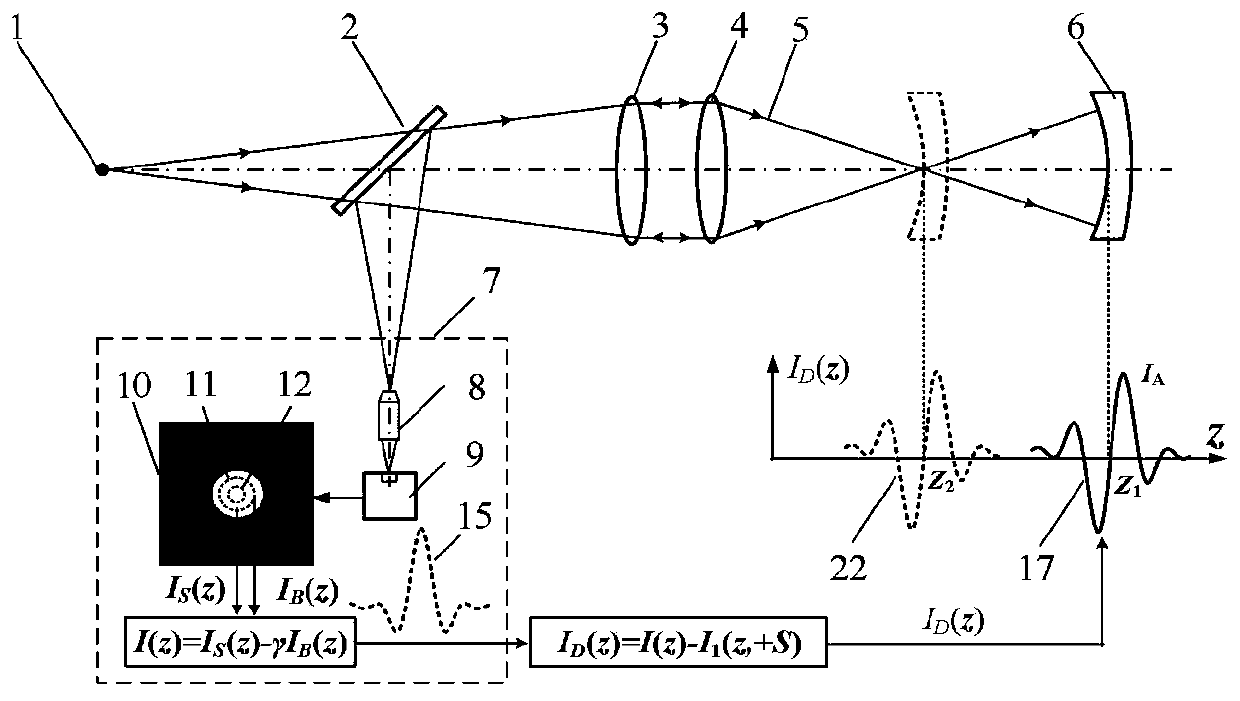
[0040] as attached Figure 5 As shown, the measurement steps of the bilateral misalignment differential confocal radius of curvature measurement method are:

[0041] 1) start the measurement software of main control computer 24, turn on laser device 28, the light that laser device (28) sends forms point light source 1 after microscopic objective lens 29 and pinhole 30; Common optical axis with collimator lens 3;

[0042] 2) The light emitted by the point light source 1 passes through the beam splitter 2, the collimator lens 3 and the measuring objective lens 4, and then converges into a focused measuring beam 5, which is irradiated on the spherical mirror 6 to be tested, and the focused measuring beam 5 reflected by the surface of the spherical mirror 6 to be tested is then After the measurement objective lens 4 and the collimating lens 3, it is reflected by the beam splitter 2 and enters the transverse subtraction confocal detection system 7, and the measurement software in ...


PUM


Abstract

The invention belongs to the technical field of optical precision measurement and relates to a method for measuring a bilateral dislocation differential confocal radius of curvature. In a confocal measurement optical path system, the method comprises the following steps: firstly, in an airy disk image detected by a CCD, a large virtual pinhole detection area and a small virtual pinhole detection area are set through software, the two detected confocal characteristic curves are subjected to subtraction processing so as to sharpen the confocal characteristic curves, then, the sharpened confocalcharacteristic curves are subjected to bilateral dislocation differential subtraction processing to obtain an axial high-sensitivity differential confocal characteristic curve, and finally, the characteristic of accurate correspondence of the bilateral dislocation differential confocal characteristic curve zero point and the focal point of the confocal measurement system is used to carry out high-precision focus fixing and addressing on the "cat eye" and "confocal" positions of the measured sphere, so as to improve the focus fixing accuracy in the measurement of the spherical radius of curvature. Compared with the existing radius-of-curvature method, the method has the advantages of high measurement accuracy, strong environmental interference resistance, simple structure and the like and has wide application prospects in the technical field of optical precision measurement.

Description

technical field [0001] The invention relates to a bilateral misalignment differential confocal curvature radius measurement method, which can be used for non-contact high-precision measurement of the curvature radius of a spherical element and belongs to the technical field of optical precision measurement. Background technique [0002] In optical systems, inertial navigation systems, and aircraft engine transmission systems, spherical elements are one of the most important elements. The radius of curvature of the spherical element is the most critical parameter to determine the overall performance of the element, so it is of great significance to measure the radius of curvature of the spherical element with high precision. [0003] For the measurement of the radius of curvature of a spherical surface, the existing measurement methods are: spherical template method, spherometer method, self-collimation method, interferometer method, knife-edge meter method, Newton ring metho...

Claims


Application Information

Patent Timeline
IPC IPC(8): G01B11/255
CPCG01B11/255
Inventor 赵维谦邱丽荣
Owner BEIJING INSTITUTE OF TECHNOLOGYGY
Why Eureka
Try Eureka