Guide type turnout in monorail, crossover turnout and rail transit system
A technology of internal guidance and turnouts, which is applied in the direction of tracks, hydraulic equipment for operating turnouts or line breakers, and electrical equipment for operating turnouts or line breakers. It can solve the problem of easy damage of turnout beams, heavy turnout beams Turnout beam operation is time-consuming and labor-intensive, and achieves the effect of good economy, simple structure and high reliability
- Summary
- Abstract
- Description
- Claims
- Application Information
AI Technical Summary
Problems solved by technology
Method used
Image
Examples
Embodiment 1
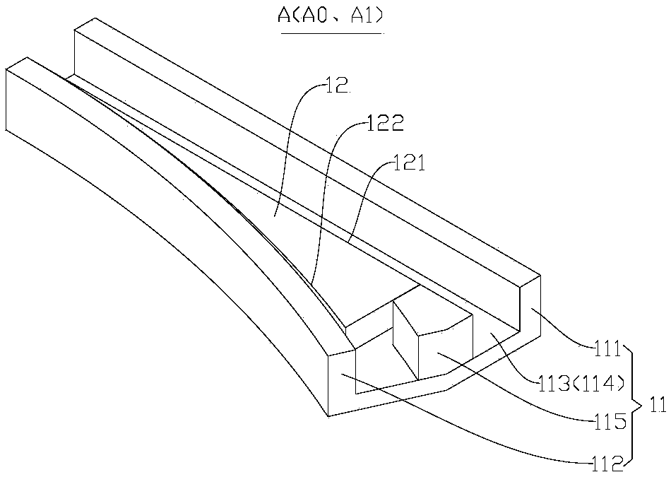
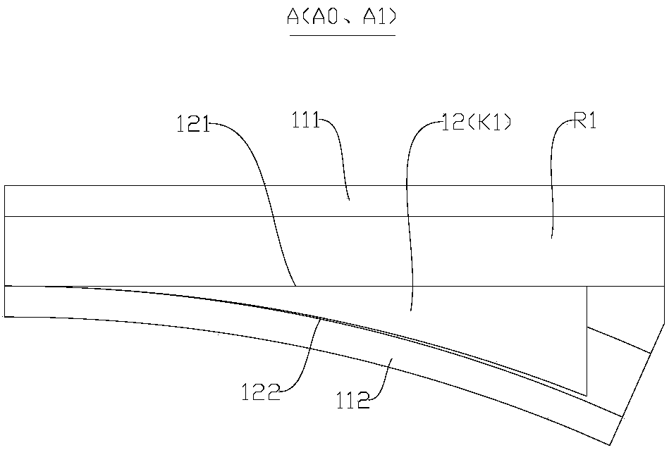
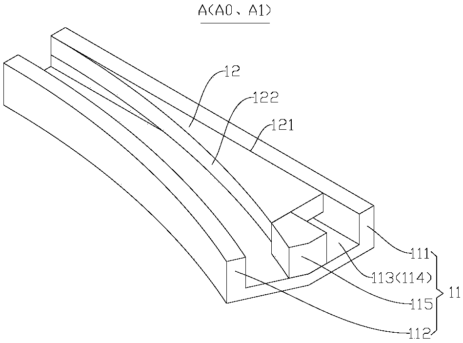
[0175] Such as Figure 33-Figure 40 As shown, the fixed beam 11 includes a connecting beam 114 connected between the first side beam 111 and the second side beam 112, and the movable beam 12 is installed with a rolling device between the movable beam 12 and the connecting beam 114. Thus, during the movement of the movable beam 12 relative to the fixed beam 11, the movable beam 12 can form a rolling friction fit with the connecting beam 114 through the rolling device, thereby reducing friction resistance and friction loss, and improving the portability and ease of movement of the movable beam 12 Reliability and reduced friction damage.
[0176] Preferably, as Figure 33 As shown, the above-mentioned connecting beam 114 can be used as the supporting wall of the traffic channel (that is, the supporting beam 113 described above). For example, when the monorail inner-guided switch A is a riding switch, the connecting beam 114 can be used as the bottom of the traffic channel. When the ...
Embodiment 2
[0193] The second embodiment is substantially the same as the above-mentioned embodiment, and the same components are given the same reference numerals. The difference is that the driving device of the second embodiment is different from the driving device of the first embodiment.
[0194] Such as Figure 46-Figure 51 As shown, the driving device 3 includes: a first connecting rod 321, a second connecting rod 322, and a driving cylinder 323 (for example, an electric cylinder, an air cylinder, or a hydraulic cylinder). The first end of the first connecting rod 321 is hinged with the movable beam 12, The two ends of the two connecting rods 322 are respectively hinged with the second end of the first connecting rod 321 and the fixed beam 11. The driving cylinder 323 includes a cylinder tube 3231 arranged on the fixed beam 11 and a free end that can be translated along the cylinder tube 3231 and the second end. The push rod 3232 hinged with the two connecting rods 322, that is to say,...
Embodiment 3
[0198] The third embodiment is substantially the same as the above-mentioned embodiment, and the same components are given the same reference numerals. The difference is that the driving device of the third embodiment is different from the driving device of the first embodiment.
[0199] Such as Figure 52 As shown, the driving device 3 is: a driving motor 33, and the output shaft of the driving motor 33 is directly connected to the first rolling wheel 511 to drive the first rolling wheel 511 to roll on the connecting beam 114, that is, when the driving motor 33 outputs rotation At a moment, the first rolling wheel 511 can roll, thereby driving the first trolley 61 and the movable beam 12 to travel. Therefore, the direct drive of the motor 3111 can further simplify the structure and improve the reliability of control, and the installation of the drive device 3 is simple, economical, and convenient to maintain. Preferably, the driving motor 33 is installed on the movable beam 12 a...
PUM
 Abstract
Description
Claims
Application Information
 - Generate Ideas
- Intellectual Property
- Life Sciences
- Materials
- Tech Scout
- Unparalleled Data Quality
- Higher Quality Content
- 60% Fewer Hallucinations
Browse by: Latest US Patents, China's latest patents, Technical Efficacy Thesaurus, Application Domain, Technology Topic, Popular Technical Reports.
© 2025 PatSnap. All rights reserved.Legal|Privacy policy|Modern Slavery Act Transparency Statement|Sitemap|About US| Contact US: help@patsnap.com


