Description method for structural deformation of spaceborne microwave remote sensing instrument

A technology of structural deformation and spaceborne microwaves, applied in instruments, radio wave measurement systems, satellite radio beacon positioning systems, etc., can solve problems such as the inability to fully describe the deformation of scanning microwave imaging instruments, and achieve the effect of high-precision geometric correction

Active Publication Date: 2019-07-05
SHANGHAI SATELLITE ENG INST
View PDF9 Cites 2 Cited by
  • Summary
  • Abstract
  • Description
  • Claims
  • Application Information

AI Technical Summary

Problems solved by technology

However, this method simplifies the modeling of the internal distortion of the instrument, and cannot fully describe the deformation of the scanning microwave imaging instrument

Method used


Image

  • Description method for structural deformation of spaceborne microwave remote sensing instrument
  • Description method for structural deformation of spaceborne microwave remote sensing instrument
  • Description method for structural deformation of spaceborne microwave remote sensing instrument

Examples


Embodiment

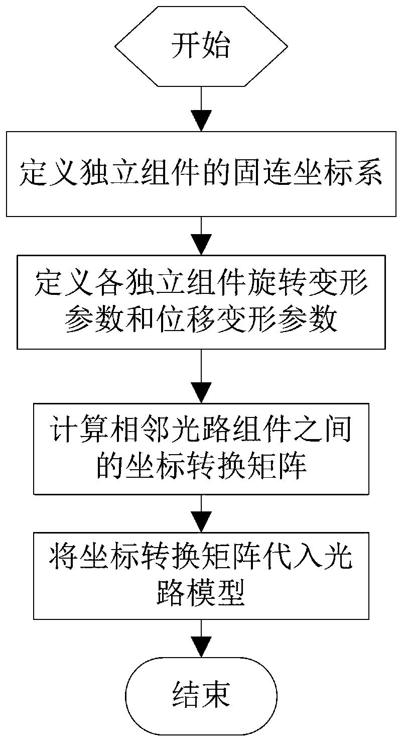
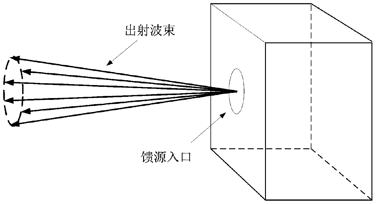
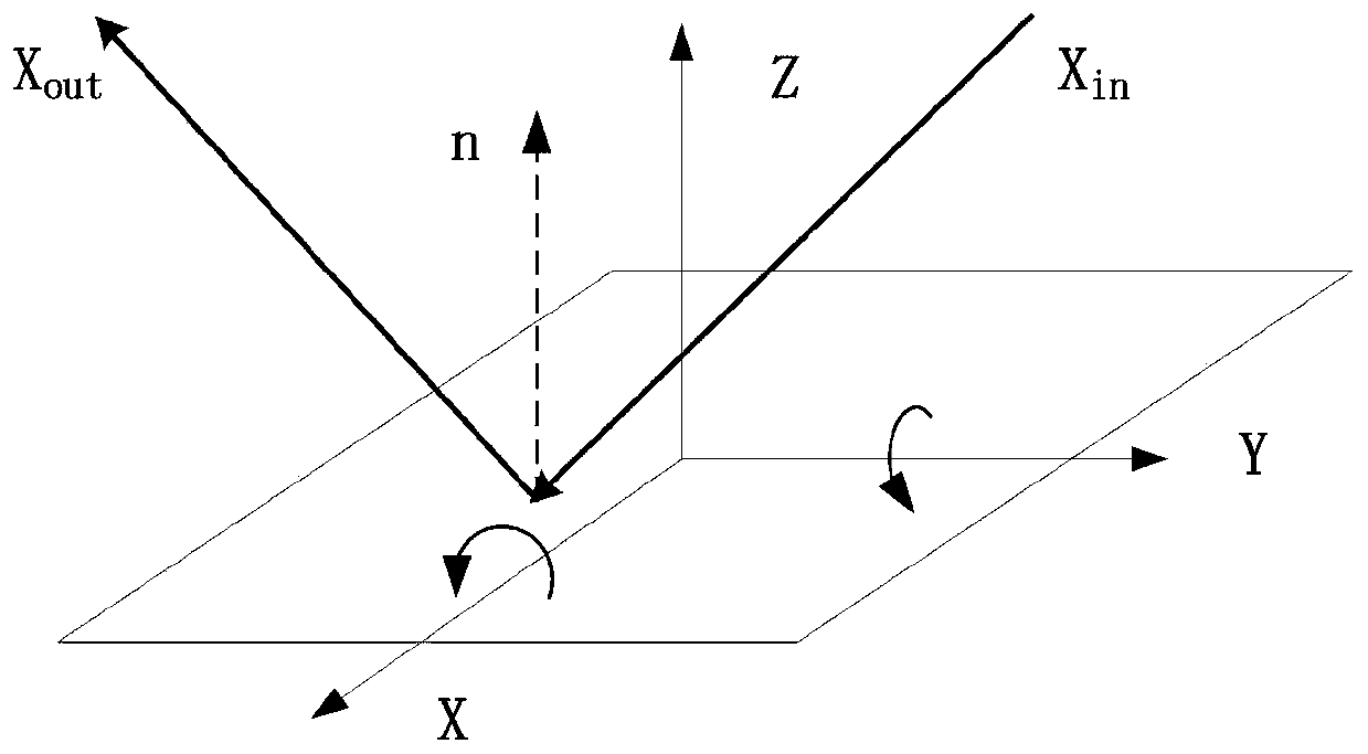
[0046] In this embodiment, the method for describing the structural deformation of the spaceborne microwave remote sensing instrument of the present invention divides the independent components of the microwave remote sensing instrument into four types of independent components: plane reflector, rotating parabolic reflector, rotated hyperboloid reflector, and feed source. Components, use the rotation deformation parameters and displacement deformation parameters to describe the component deformation, construct the coordinate transformation matrix after the component deformation according to the rotation deformation parameters and displacement deformation parameters, and use the coordinate transformation matrix to realize the line of sight state vector between the fixed coordinate systems of adjacent reflective surfaces conversion.

[0047] Next, the present invention will be described in detail.

[0048] The purpose of the present invention is to provide a description method f...


PUM


Abstract

The invention relates to a description method for the structural deformation of a spaceborne microwave remote sensing instrument in the technical field of remote sensing instrument modeling methods. The method comprises the steps that 1 a fixed coordinate system of each individual component in an instrument is defined; 2 the rotational deformation parameters and the displacement deformation parameters of each reflecting surface and a feed source are defined; 3 by starting from the feed source, a coordinate system conversion matrix between adjacent optical path components is calculated according to the rotational deformation parameters and the displacement deformation parameters of the optical path components; and 4 the coordinate system conversion matrix is substituted into an optical pathmodel. According to the description method for the structural deformation of the spaceborne microwave remote sensing instrument, the structural deformation of the spaceborne microwave remote sensinginstrument including a planar reflecting surface, a rotating parabolic reflecting surface, a rotating hyperbolic reflecting surface and other components can be described with a minimum of deformationparameters, which helps subsequent optical path modeling of the spaceborne microwave remote sensing instruments with structural deformation.

Description

technical field [0001] The invention relates to the technical field of modeling methods for remote sensing instruments, in particular to a method for describing structural deformation of spaceborne microwave remote sensing instruments. Background technique [0002] The construction of the precise satellite imaging geometric model is the core of the geometric correction scheme based on the remote sensing instrument imaging model. There are long-period and short-period changes in satellite platform attitude, orbital position, thermal environment, and mechanical environment, which make the line of sight of the instrument deviate from the nominal direction, resulting in deviations in the correspondence between image pixels and geographic locations. [0003] The attitude and orbit changes of the satellite platform can be accurately measured and then compensated or corrected. However, the on-orbit deformation mechanism of the satellite platform and instruments caused by factors su...

Claims


Application Information

Patent Timeline
Patent Type & Authority Applications(China)
IPC IPC(8): G01S19/07G01B11/16
CPCG01B11/16G01S19/07
Inventor 刘华清董瑶海周徐斌宋效正陆国平谢振超
Owner SHANGHAI SATELLITE ENG INST
Why Eureka
Try Eureka