
Method, system and control device for real-time measurement of runoff velocity

A real-time measurement and control device technology, applied in measurement devices, fluid velocity measurement, velocity/acceleration/impact measurement, etc., can solve the problems of high price, manpower and material resources, etc., to reduce measurement work, reduce personnel and equipment, save money The effect of measuring costs

Active Publication Date: 2021-12-31
WUHAN NEWFIBER OPTOELECTRONICS TECH +1
View PDF10 Cites 0 Cited by
  • Summary
  • Abstract
  • Description
  • Claims
  • Application Information

AI Technical Summary

Problems solved by technology

[0002] At present, the common method of measuring the flow velocity of the river is the use of ADCP (Acoustic Doppler Current Profilers, Acoustic Doppler Current Profilers) measurement, which can be divided into navigation type or fixed type, that is, the use of ADCP flow velocity measurement principle The vertical line in the watershed section is different The flow velocity at the point level and the average flow velocity on different vertical lines are used to calculate the overall river flow according to the flow velocity at multiple points in the section. This kind of equipment is expensive. When using it for surveying, it needs to be calibrated and debugged to input a variety of measurement parameters, which is labor-intensive. material resources

Method used


Image

  • Method, system and control device for real-time measurement of runoff velocity
  • Method, system and control device for real-time measurement of runoff velocity
  • Method, system and control device for real-time measurement of runoff velocity

Examples


Embodiment Construction

[0055] It should be understood that the specific embodiments described here are only used to explain the present invention, not to limit the present invention.

[0056] refer to figure 1 , figure 1 It is a structural schematic diagram of the real-time measurement and control device for runoff flow velocity of the present invention.

[0057] Such as figure 1As shown, the device for real-time measurement and control of runoff velocity may include: a processor 1001 , such as a CPU, a communication bus 1002 , a user interface 1003 , a network interface 1004 , and a memory 1005 . Wherein, the communication bus 1002 is used to realize connection and communication between these components. The user interface 1003 may include a display screen (Display), an input unit such as a keyboard (Keyboard), and the optional user interface 1003 may also include a standard wired interface and a wireless interface. Optionally, the network interface 1004 may include a standard wired interface a...


PUM


Abstract

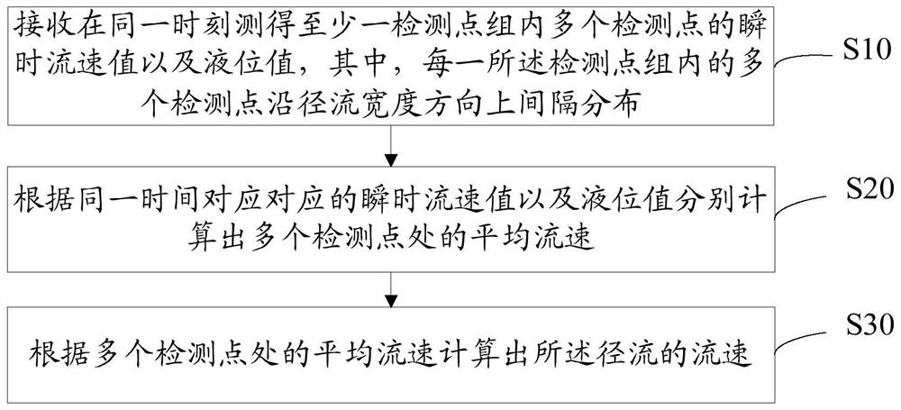
The invention discloses a method, system and control device for real-time measurement of runoff flow velocity, wherein the real-time measurement method of runoff flow velocity includes: receiving instantaneous flow velocity values ​​and liquid level values ​​of multiple detection points in at least one detection point group measured at the same time, Wherein, multiple detection points in each detection point group are distributed at intervals along the runoff width direction; according to the instantaneous flow velocity value and liquid level value of multiple detection points in the at least one detection point group, respectively calculate the described The average flow velocity at multiple detection points in at least one detection point group; calculate the flow velocity of the runoff according to the average flow velocity at multiple detection points in the at least one detection point group, and realize the real-time online measurement of the runoff flow velocity The measurement reduces the number of personnel and equipment involved in the measurement process, greatly reduces the measurement work, and saves measurement costs.

Description

technical field [0001] The invention relates to the technical field of river flow velocity measurement, in particular to a method, system and control device for real-time measurement of runoff flow velocity. Background technique [0002] At present, the common method of measuring the flow velocity of the river is the use of ADCP (Acoustic Doppler Current Profilers, Acoustic Doppler Current Profilers) measurement, which can be divided into navigation type or fixed type, that is, the use of ADCP flow velocity measurement principle The vertical line in the watershed section is different The flow velocity at the point level and the average flow velocity on different vertical lines are used to calculate the overall river flow according to the flow velocity at multiple points in the section. This kind of equipment is expensive. When using it for surveying, it needs to be calibrated and debugged to input a variety of measurement parameters, which is labor-intensive. physical resour...

Claims


Application Information

Patent Timeline
Patent Type & Authority Patents(China)
IPC IPC(8): G01P5/24
CPCG01P5/241
Inventor 潘凌武治国李立青张家铨沈海超陈银游政园徐锦峰
Owner WUHAN NEWFIBER OPTOELECTRONICS TECH
Learn More