
Thermionic triode and heat circuit

A technology of triode and hot pole, which is applied in the thermal field to achieve the effect of thermal rectification

Active Publication Date: 2019-07-05
TSINGHUA UNIV +1
View PDF4 Cites 4 Cited by
  • Summary
  • Abstract
  • Description
  • Claims
  • Application Information

AI Technical Summary

Problems solved by technology

However, in the prior art, there is no method for effectively controlling the interface thermal resistance and a thermal device with adjustable interface thermal resistance.

Method used


Image

  • Thermionic triode and heat circuit
  • Thermionic triode and heat circuit
  • Thermionic triode and heat circuit

Examples


Embodiment Construction

[0035] The present invention will be further described in detail below in conjunction with the accompanying drawings and specific embodiments.

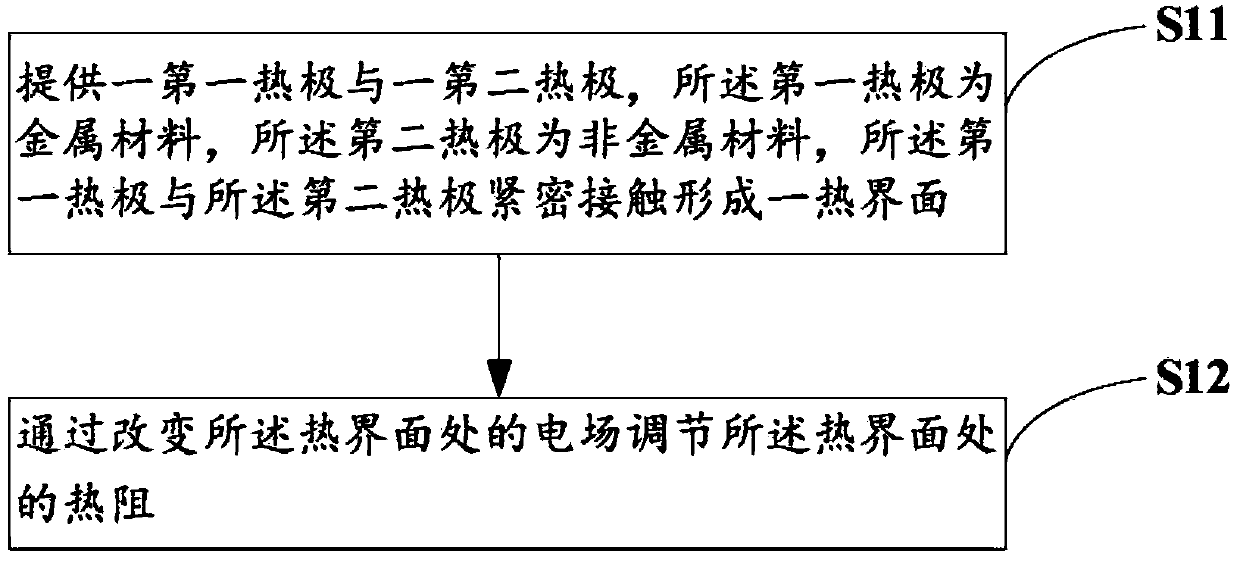
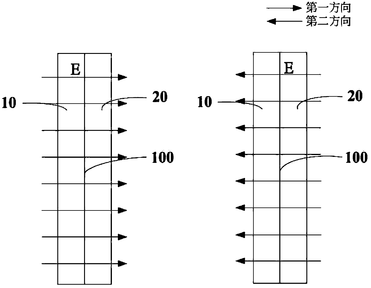
[0036] see Figure 1-2 , the embodiment of the present invention provides a method for regulating the thermal resistance of the interface, which is used for regulating the thermal resistance at the interface between a metal material and a non-metal material. The control methods include:

[0037] Step S11, providing a first heating electrode 10 and a second heating electrode 20, the first heating electrode 10 is made of a metal material, the second heating electrode 20 is made of a non-metallic material, and the first heating electrode 20 is made of a metal material. pole 10 is in close contact with said second thermal pole 20 to form a thermal interface 100; and

[0038] Step S12 , adjusting the thermal resistance at the thermal interface 100 by changing the electric field strength (direction and / or strength) at the thermal interfac...


PUM


Abstract

The invention provides a thermionic triode. The thermionic triode comprises a first thermal pole, a second thermal pole and a thermal resistance regulating unit. The first thermal pole is made of a metallic material. The second thermal pole is made of a non-metallic material. The first thermal pole and the second thermal pole make close contact to form a thermal interface. The thermal resistance regulating unit is used for forming a regulation and control electric field at the thermal interface. The thermionic triode provided by the invention is simple in structure, effectively realizes thermal rectification and makes it possible to further manufacture various types of thermal logic devices.

Description

technical field [0001] The invention relates to the technical field of heat, in particular to a thermal triode. Background technique [0002] When heat flows through the interface of two contacting solids, the interface itself presents an obvious thermal resistance to heat flow, that is, interfacial thermal resistance. Thermal logic control can be realized by adjusting the size of the interface thermal resistance, and thermal devices can be manufactured on this basis. However, in the prior art, there is no method for effectively controlling the thermal interface resistance and a thermal device with adjustable interface thermal resistance. Contents of the invention [0003] In view of this, it is indeed necessary to provide a thermal triode to overcome the deficiencies in the prior art. [0004] A thermal triode, comprising: a first thermal pole and a second thermal pole, the first thermal pole is made of metal material, the second thermal pole is made of non-metallic mat...

Claims


Application Information

Patent Timeline
Patent Type & Authority Applications(China)
IPC IPC(8): F28F13/16
CPCF28F13/16F28F2013/008F28F2255/06F28F2255/20H01L23/373H01L23/3736F28C3/005F28F2013/001
Inventor 段正刘长洪范守善
Owner TSINGHUA UNIV
Learn More