A centrifugal fan volute
A centrifugal fan and volute technology, which is applied in mechanical equipment, machines/engines, liquid fuel engines, etc., can solve the problem that the actual flow rate of the user with the maximum static pressure drops, solid droplets are easily formed at the volute tongue, and the flow field at the volute inlet is not stable. Uniformity and other issues to achieve the effect of increasing static pressure, improving fluency, and reducing accumulation
- Summary
- Abstract
- Description
- Claims
- Application Information
AI Technical Summary
Problems solved by technology
Method used
Image

Examples
Embodiment 1
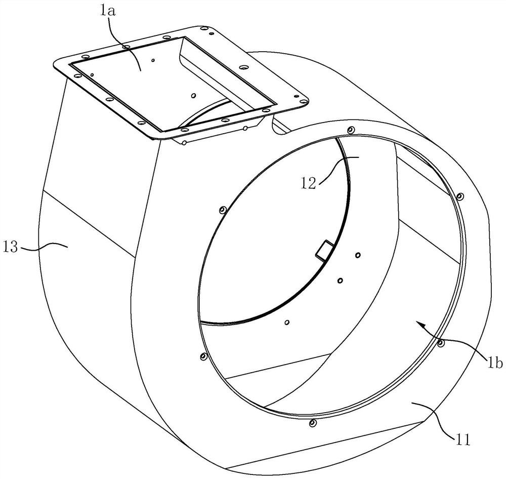
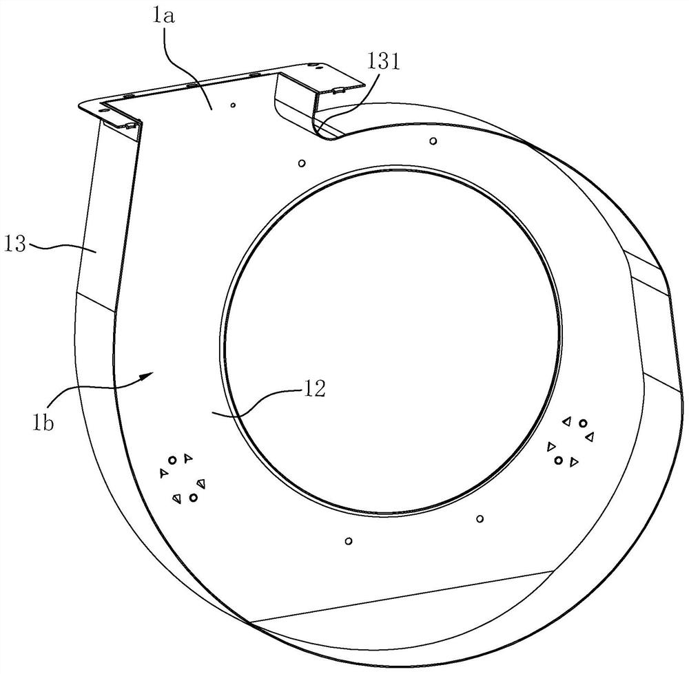
[0025] Such as Figure 1 to Figure 3Shown is the first embodiment of the present invention. The centrifugal fan volute used for range hoods in this embodiment includes a front cover 11, a rear cover 12, and a ring wall enclosure 13 connecting the front cover 11 and the rear cover 12. The above-mentioned front cover 11 , the rear cover plate 12 and the surrounding wall panel 13 form a cavity 1b with an air outlet 1a on the top, the cavity 1b is used to accommodate the impeller, the air outlet 1a is located at the top of the volute, and the inner wall of the volute is adjacent to the outlet The position of the tuyere 1a has a volute tongue 131 protruding into the cavity 1b, and the volute tongue 131 is recessed inwardly relative to the outer wall of the volute, that is, a shallow volute tongue or an indented volute tongue, and the volute tongue 131 is formed on the annular coaming 13, the ring wall coaming 13 is an integral profile, and the volute tongue 131 is located at the s...
Embodiment 2
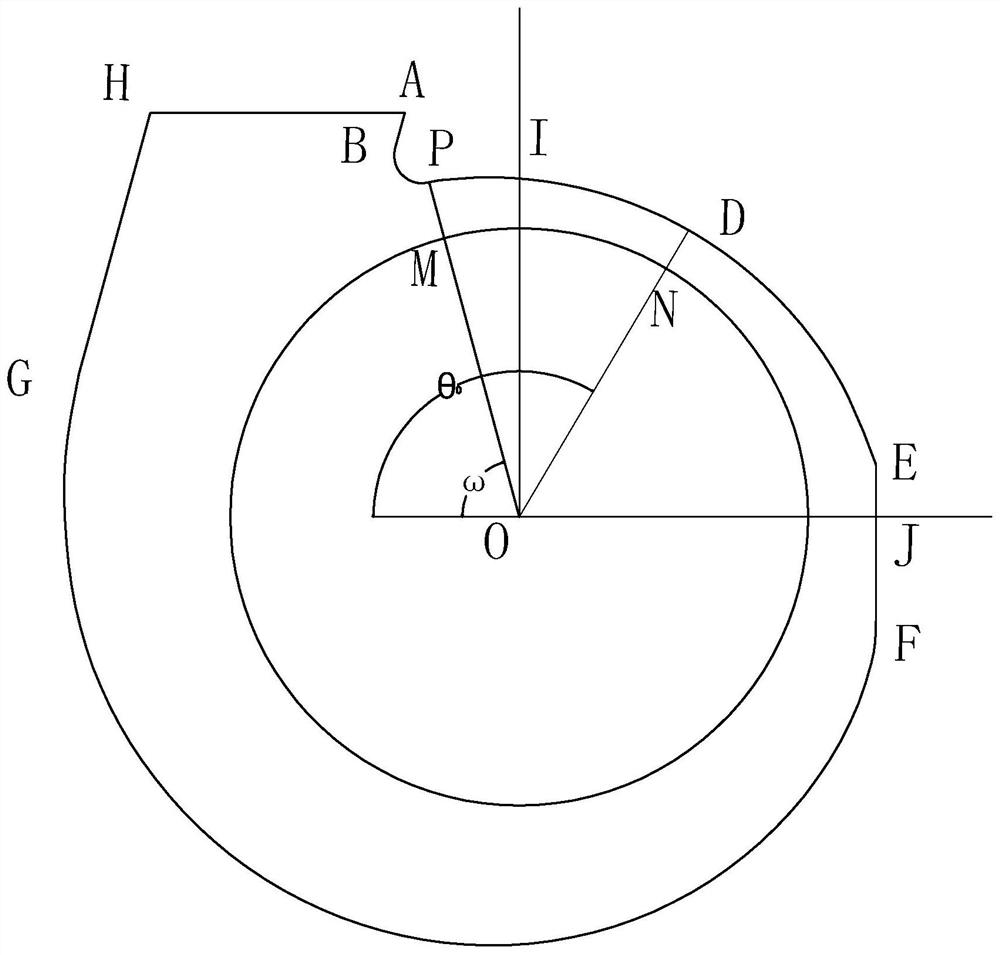
[0030] Such as Figure 4 Shown is the second embodiment of the present invention. The only difference between this embodiment and the first embodiment is that the second connecting line DG is a logarithmic helix with a variable divergence angle. Specifically, the pole radius of the second connection line DG Among them, the variable expansion angle alpha 1 and alpha 2 Both ∈ [3°,9°], and α 1 ≥α 2 , The adjustment item s ∈ [-0.5, 0.5], r ∈ [-5, 5] and r≠1, α 1 is the expansion angle of D, α 2 is the expansion angle of point G, is the wrap angle corresponding to the variable helix, θ 0 is the angle formed by the connecting line OD and the horizontal line passing through point O on the side adjacent to the air outlet, θ is the polar coordinate angle variable of any point on the second connecting line DG, R 2 is the outer diameter of the impeller. The second connecting line DG adopts a helical line with variable angle, which can more conveniently control the expansi...
PUM
 Abstract
Description
Claims
Application Information
 - R&D
- Intellectual Property
- Life Sciences
- Materials
- Tech Scout
- Unparalleled Data Quality
- Higher Quality Content
- 60% Fewer Hallucinations
Browse by: Latest US Patents, China's latest patents, Technical Efficacy Thesaurus, Application Domain, Technology Topic, Popular Technical Reports.
© 2025 PatSnap. All rights reserved.Legal|Privacy policy|Modern Slavery Act Transparency Statement|Sitemap|About US| Contact US: help@patsnap.com