
Prefabricated building connection assembly

A technology of connecting components and assembling, which is applied in the direction of building components, buildings, building structures, etc. It can solve the problems of inconvenient adjustment, external movement of external hanging panels, and insufficient connection effect, etc., to achieve enhanced stability, convenient disassembly and recovery, and improved repetition. The effect of utilization

Inactive Publication Date: 2019-07-05
山东汇源杭萧钢构有限公司
View PDF7 Cites 4 Cited by
  • Summary
  • Abstract
  • Description
  • Claims
  • Application Information

AI Technical Summary

Problems solved by technology

[0004] Similarly, prefabricated concrete buildings also have deficiencies during the construction process. The joints still need to be poured twice during the stone red process. During the pouring construction, it is easy to appear at the place where the concrete is poured and cause it to be used as a shear wall. The external hanging panels of the external formwork of the external formwork appear to move outwards, so the connection strength of the entire building structure needs to be strengthened after installing the assembled external formwork and before pouring
The existing connectors have insufficient connection effect when performing cast-in-place connections on walls, are inconvenient to adjust, and cannot well prevent the external movement of external hanging panels.

Method used


Image

  • Prefabricated building connection assembly
  • Prefabricated building connection assembly
  • Prefabricated building connection assembly

Examples


Embodiment Construction

[0026] Embodiments of the technical solutions of the present invention will be described in detail below in conjunction with the accompanying drawings. The following examples are only used to illustrate the technical solutions of the present invention more clearly, and therefore are only examples, rather than limiting the protection scope of the present invention.

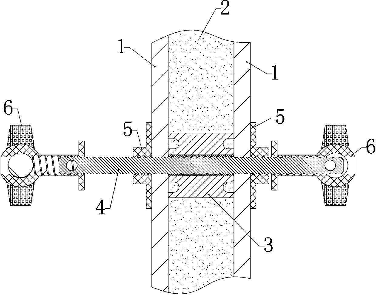
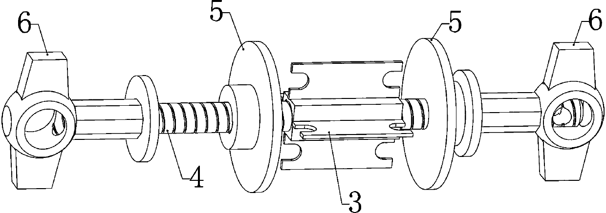
[0027] Such as Figure 1-8 As shown in , a prefabricated building connection assembly includes an outer casing 3 arranged inside the cast-in-place concrete layer 2 between two prefabricated formworks 1, and the two ends of the outer casing 3 are respectively pressed against the corresponding prefabricated formwork On the inner side wall of the formwork 1, a tension screw 4 is co-located in the outer sleeve 3, and both ends of the tension screw 4 move through the assembled formwork 1 on the corresponding side, and on the outside of each assembled formwork 1 A T-shaped helical tube 5 is respectively screwed together...


PUM


Abstract

The invention relates to the field of building construction, in particular to a prefabricated concrete building connecting part,and specifically discloses a prefabricated building connection assembly.The prefabricated building connection assembly comprises an outer kit ina cast-in-place concrete layer, the outer kit isarrangedon the outside and between two prefabricated formworks, and the two ends of the outer kitabut against the inner side wall of the corresponding prefabricated formworks correspondingly; a tensioning screw is arranged in the outer kit in a matching mode, the two ends of thetensioning screw both penetrate out of the prefabricated formwork of the corresponding side in a movable mode,and a T-shaped solenoid is screwed on the tensioning screws on the outer sides of each ofthe prefabricated formworks correspondingly. By arranging the T-shaped solenoids at the two ends of the tensioning screws and two fastening members abutting the solenoids, the probability of the T-shaped solenoids rotating outwards and rotating out can be effectively reduced, the stability of connection is enhanced, and the outward moving risk of the formworks is reduced; at the same time the outer kit is arranged to facilitate the recycling of every other remaining component after a later period construction is completed, disassembly and recycling are convenient, and the reusing rate of thecomponents is increased.

Description

technical field [0001] The invention relates to the field of building construction, in particular to a prefabricated concrete building connector, especially a prefabricated building connector component. Background technique [0002] Prefabricated concrete buildings refer to concrete structure buildings designed and constructed through on-site assembly of reinforced concrete prefabricated components mainly produced in factories. It is generally divided into two categories: fully assembled buildings and partially assembled buildings: fully assembled buildings are generally low-rise or multi-storey buildings with low seismic fortification requirements; the main components of partially assembled buildings are generally prefabricated components, which are connected by cast-in-place concrete on site. A building that forms an assembled monolithic structure. The characteristics of the building are that the construction speed is fast, it is beneficial to winter construction, the pro...

Claims


Application Information

Patent Timeline
Patent Type & Authority Applications(China)
IPC IPC(8): E04B2/86
CPCE04B2/86E04B2/8647
Inventor 刘洪波唐延旭张恒韩贺贺
Owner 山东汇源杭萧钢构有限公司
Learn More