
Prefabricated pipe gallery mechanical and hydraulic combined type overall installation and disassembly steel formwork and installation method

A steel formwork and combined technology, applied in water conservancy projects, artificial islands, underwater structures, etc., can solve the problems of low dimensional accuracy of formwork installation, poor formwork joints, and difficulty in formwork installation and dismantling, so as to avoid leakage. The effect of pulp phenomenon, material saving and considerable benefit

Pending Publication Date: 2019-07-05
中铁二十二局集团第三工程有限公司 +1
View PDF0 Cites 5 Cited by
  • Summary
  • Abstract
  • Description
  • Claims
  • Application Information

AI Technical Summary

Problems solved by technology

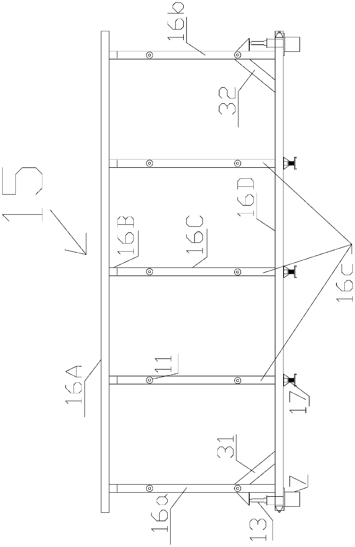
[0005] The purpose of the present invention is to solve the problems existing in the prior art, and to provide a prefabricated pipe gallery mechanical and hydraulic combined type integral installation and disassembly steel formwork and installation method. The top plate of the wall body uses chamfered steel formwork plus wood formwork system and ordinary steel formwork cannot be cast as a whole at one time, the joints of the formwork are not tight, the dimensional accuracy of the formwork is not high, the installation and disassembly of the formwork is difficult, the formwork is easy to deform, and large-scale machinery is required to cooperate with the formwork installation, etc. technical challenge

Method used


Image

  • Prefabricated pipe gallery mechanical and hydraulic combined type overall installation and disassembly steel formwork and installation method
  • Prefabricated pipe gallery mechanical and hydraulic combined type overall installation and disassembly steel formwork and installation method
  • Prefabricated pipe gallery mechanical and hydraulic combined type overall installation and disassembly steel formwork and installation method

Examples


Embodiment Construction

[0036] In order to make the technical problems to be solved by the present invention, technical solutions and beneficial effects clearer and clearer, the present invention will be described in further detail below in conjunction with the accompanying drawings and embodiments. It should be understood that the specific embodiments described here are only used to explain the present invention, not to limit the present invention.

[0037] In the claims, description and the above drawings of the present invention, unless otherwise clearly defined, the terms "first", "second" or "third" are used to distinguish different objects, not for Describe a specific order.

[0038] In the claims, specification and above-mentioned drawings of the present invention, unless otherwise clearly defined, for orientation words, such as the use of the terms "center", "lateral", "longitudinal", "horizontal", "vertical", "top" , "Bottom", "Inner", "Outer", "Up", "Down", "Front", "Back", "Left", "Right"...


PUM


Abstract

The invention discloses a prefabricated pipe gallery mechanical and hydraulic combined type overall installation and disassembly steel formwork and an installation method. An outer mold steel pulley matched with an outer mold steel track is installed under an outer support truss of an outer mold support system. An inner mold steel formwork of an inner mold support system includes a top mold, sidemolds and lower chamfering molds which are hinged as a whole; a first mechanical spiral expansion machine of an inner mold installation and disassembly system is connected with a vertical frame body and the side molds, a second mechanical spiral expansion machine is mounted on the vertical frame body, and a third mechanical spiral expansion machine is connected with the side molds and the lower chamfering molds; and the inner mold installation and disassembly system further includes chain blocks with one ends fixed to the side molds and the other ends used for hooking the lower chamfering molds during demolding. The installation and disassembly steel formwork can solve the technical problems that one-time overall pouring molding cannot be achieved, the formwork joint is not tight, the formwork installation dimensional accuracy is not high, the formwork is difficult to install and disassemble, the formwork is prone to deforming and large-scale machines need to be matched with the formwork installation when a standard prefabricated reinforced concrete box-type component bottom plate and a wall top plate use a chamfer steel mold and wood mold system and a normal steel formwork.

Description

technical field [0001] The invention relates to an integral cast-in-place steel formwork system for the main body of the prefabricated pipe gallery structure. The support system can solve the problem that the bottom plate of the standard prefabricated reinforced concrete box-shaped member and the top plate of the wall body cannot be integrally poured at one time by using the chamfered steel formwork plus wooden formwork system and ordinary steel formwork. There are technical problems such as loose formwork joints, low dimensional accuracy of formwork installation, difficulty in formwork installation and disassembly, easy deformation of formwork, and the need for large-scale machinery to cooperate with formwork installation. The present invention is particularly applicable to the construction of prefabricated reinforced concrete box components. Background technique [0002] The comprehensive pipeline corridor is the comprehensive corridor of underground urban pipelines. That...

Claims


Application Information

Patent Timeline
Patent Type & Authority Applications(China)
IPC IPC(8): E02D29/045
CPCE02D29/10Y02E10/20
Inventor 钟焕富张彦民王新荣郑一明曾亮邓燕
Owner 中铁二十二局集团第三工程有限公司
Learn More