
Clamping mechanism for corrugated roller processing

A technology of clamping mechanism and corrugating roller, which is applied in metal processing equipment, manufacturing tools, grinding workpiece supports, etc. The effect of using efficiency

Pending Publication Date: 2019-07-05
SHANGHAI DASONG CORRUGATING ROLL IND
View PDF0 Cites 2 Cited by
  • Summary
  • Abstract
  • Description
  • Claims
  • Application Information

AI Technical Summary

Problems solved by technology

[0002] The corrugating roll is the most important part of the corrugated cardboard production equipment. When the traditional corrugating roll is polished and repaired on its surface, it needs to be fixed and clamped by external maintenance equipment to keep the main body of the corrugating roll stable. Traditional corrugating rolls are used for processing The operation of the clamping mechanism is complicated and the function is single. The user needs to select the corresponding size of the clamping mechanism or the corresponding supporting clamping equipment according to the size and specification of the main body of the corrugating roller, so as to reduce the maintenance and processing time of the corrugating roller and also affect the processing efficiency of the corrugating roller. progress and timing;

Method used


Image

  • Clamping mechanism for corrugated roller processing
  • Clamping mechanism for corrugated roller processing
  • Clamping mechanism for corrugated roller processing

Examples


Embodiment Construction

[0029] The technical solutions in the embodiments of the present invention will be clearly and completely described below in conjunction with the accompanying drawings in the embodiments of the present invention. Apparently, the described embodiments are only some, not all, embodiments of the present invention. Based on the embodiments of the present invention, all other embodiments obtained by persons of ordinary skill in the art without making creative efforts belong to the protection scope of the present invention.

[0030] see Figure 1-5 , the present invention provides a technical solution:

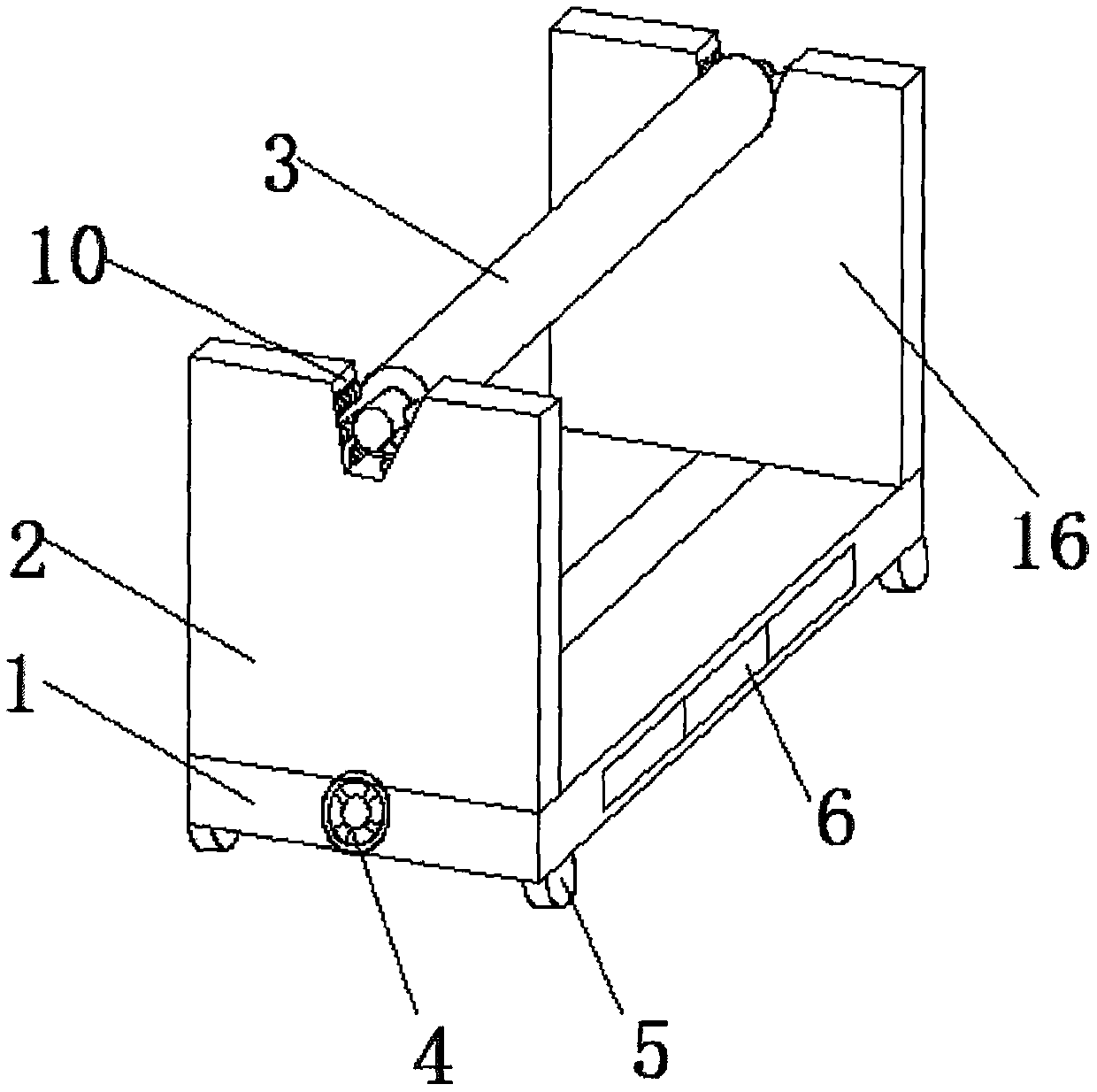
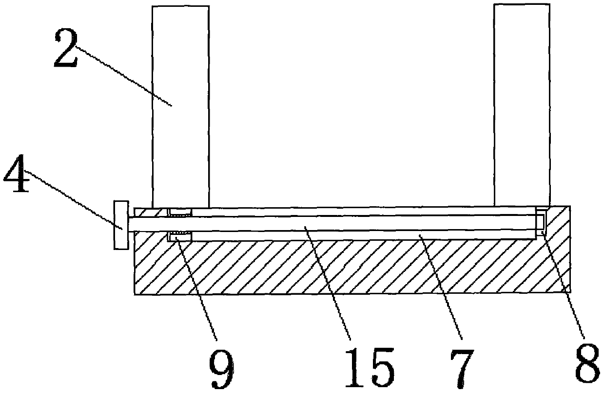
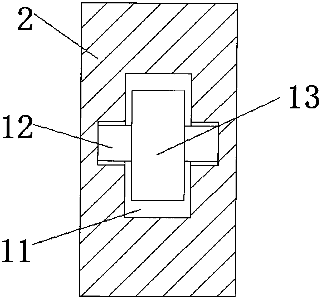
[0031] Such as figure 1 and Figure 5 As shown, a clamping mechanism for corrugated roll processing includes a base 1, the upper outer surface of the base 1 is provided with a first side plate 2 near the front end, and the upper outer surface of the base 1 is fixed near the rear end. A second side plate 16 is connected, a corrugating roller main body 3 is arranged between the fir...


PUM


Abstract

The invention discloses a clamping mechanism for corrugated roller processing. The clamping mechanism includes a base. A first side plate is arranged at the position, near the front end, of the outersurface of the upper end of the base. A sliding block is fixedly connected with the middle of the outer surface of the lower end of the first side plate. A sliding groove is formed in the position, corresponding to the sliding block, of the outer surface of the upper end of the base. A circular handle is arranged on the outer surface of the front end of the base. A threaded rod is fixedly connected to the outer surface of the rear end of the circular handle. One end of the threaded rod successively penetrates the base and the sliding block, and extends to one end of the sliding groove. The other end of the threaded rod is fixedly connected to a second bearing. According to the clamping mechanism for the corrugated roller processing, the distance between the first side plate and a second side plate can be adjusted according to the length of a corrugated roller main body. At the same time, the design structure of a trapezoidal groove and a first bearing can automatically clamp the corrugated roller main body, and thus the clamping mechanism is suitable for processing of the corrugated roller main bodies of various types and sizes, and use efficiency of a device can be better improved.

Description

technical field [0001] The invention relates to the technical field of clamping mechanisms for corrugated rolls, in particular to a clamping mechanism for processing corrugated rolls. Background technique [0002] The corrugating roll is the most important part of the corrugated cardboard production equipment. When the traditional corrugating roll is polished and repaired on its surface, it needs to be fixed and clamped by external maintenance equipment to keep the main body of the corrugating roll stable. Traditional corrugating rolls are used for processing The operation of the clamping mechanism is complicated and the function is single. The user needs to select the corresponding size of the clamping mechanism or the corresponding supporting clamping equipment according to the size and specification of the main body of the corrugating roller, so as to reduce the maintenance and processing time of the corrugating roller and also affect the processing efficiency of the corru...

Claims


Application Information

Patent Timeline
Patent Type & Authority Applications(China)
IPC IPC(8): B24B41/06B24B41/00
CPCB24B41/00B24B41/06
Inventor 吴小峰查方进顾锋明
Owner SHANGHAI DASONG CORRUGATING ROLL IND
Learn More