


Quick Research
Generate reliable direction feasibility study reports for your R&D in just a few steps.

Technical Q&A
Discover and master advanced knowledge NOW. Basics, ideas, possibilities, all at once.

Find Solutions
As an expert in R&D theories, this can generate solutions to your technical problems instantly.

Evaluate Feasibility
Analyze your overall solution with one click, know your potential R&D risks in advance.

Monitor Landscape
Get weekly tech updates, stay abreast of the latest tech innovations and key insights.
Safety prompting system and method for implanting device in MR imaging system
A technology of an implanted device and an imaging system, applied in the field of medical testing, can solve problems such as the inability to effectively avoid safety accidents and the inability to implant the device safety indication.
- Summary
- Abstract
- Description
- Claims
- Application Information
AI Technical Summary
Problems solved by technology
Method used
Image

Examples
Embodiment 1
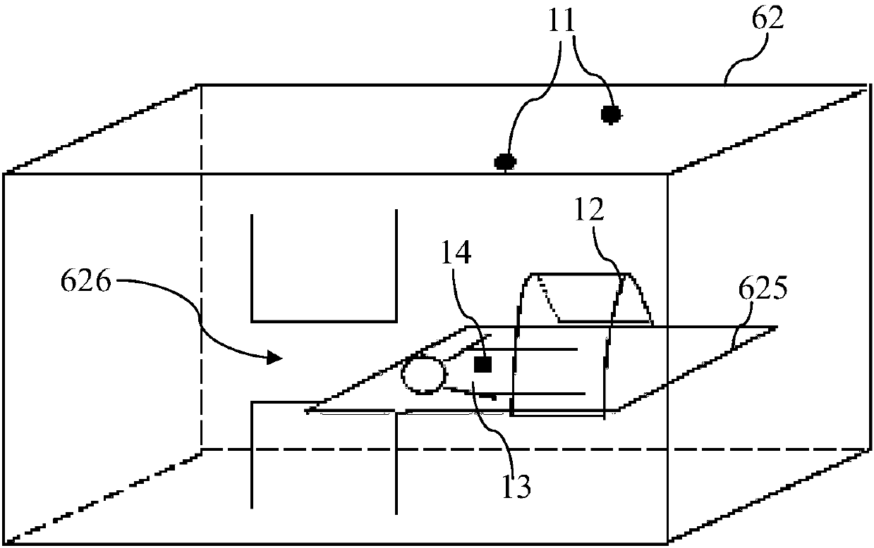
[0025] figure 1 It is a structural schematic diagram of a safety reminder system for implanted devices in the MR imaging system according to the first embodiment of the present invention, Figure 6 A block diagram of the MR imaging system is exemplarily shown.
[0026] combine figure 1 , Figure 6 As shown, the above-mentioned MR imaging system includes a scanning device located in the scanning room 62, and the scanning device 62 includes a main magnet 621 for generating a main magnetic field B0, a gradient coil 622 for linearly changing the main magnetic field B0, and a radio frequency coil 623 ( It includes a radio frequency transmitting coil for exciting the object to be detected to generate magnetic resonance and a radio frequency receiving coil for receiving the magnetic resonance signal generated by the object to be detected), and a support bed for carrying the object to be detected, and the surface of the support bed is formed The support surface 625 of the object to...
Embodiment 2
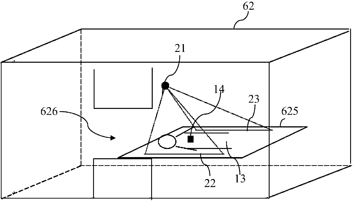
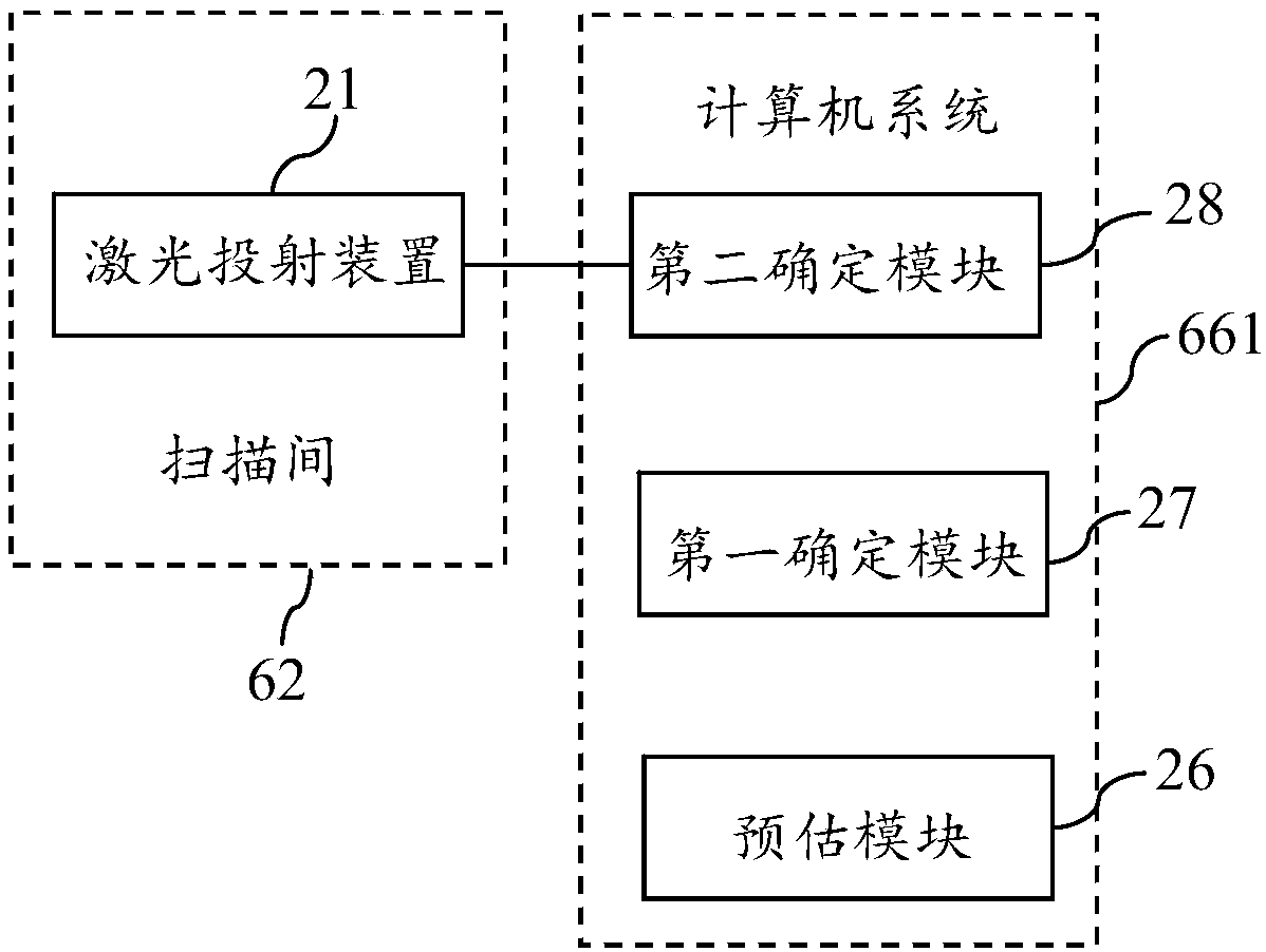
[0039] figure 2 It is a schematic structural diagram of a safety reminder system for implanted devices provided in the second embodiment of the present invention, image 3 It is a schematic block diagram of a safety reminder system for an implant device provided in the second embodiment of the present invention. The safety reminder system for implanted devices in this embodiment includes an indicating device, which indicates the positional relationship between the implanted device of the detected object and the safety boundary by indicating a predetermined safety boundary, wherein the safety boundary The position range defined by the boundary is located in a columnar spatial region that allows the implant device to enter in the main magnetic field spatial gradient intensity distribution region of the MR imaging system. The above-mentioned columnar spatial region has been explained in the first embodiment, and will not be repeated here.
[0040] The principle and implementat...
Embodiment 3
[0052] Figure 4 It is a schematic structural diagram of a safety reminder system for implanted devices provided by the third embodiment of the present invention, Figure 5 It is a schematic block diagram of a safety reminder system for an implant device provided in the third embodiment of the present invention. combine Figure 4 , Figure 6 , Figure 7 As shown, the safety reminder system for the implanted device in this embodiment includes an indicating device, and the indicating device indicates the positional relationship between the implanted device of the detected object and the safety boundary by indicating the predetermined safety boundary, wherein , the position range defined by the safety boundary is located in a columnar spatial region that allows the implant device to enter in the main magnetic field spatial gradient intensity distribution region of the MR imaging system.
[0053] In this embodiment, the safety boundary includes the vertical mapping line of two...
PUM
 Abstract
Description
Claims
Application Information
 - R&D Engineer
- R&D Manager
- IP Professional
- Industry Leading Data Capabilities
- Powerful AI technology
- Patent DNA Extraction
Browse by: Latest US Patents, China's latest patents, Technical Efficacy Thesaurus, Application Domain, Technology Topic, Popular Technical Reports.
© 2024 PatSnap. All rights reserved.Legal|Privacy policy|Modern Slavery Act Transparency Statement|Sitemap|About US| Contact US: help@patsnap.com