
Windshield wiper device

A wiper and wiper arm technology, which is used in transportation and packaging, vehicle cleaning, vehicle maintenance, etc., can solve the problems of difficult sensor wiring processing, unclear sensor installation direction, etc., and achieve the effect of suppressing chatter vibration

Inactive Publication Date: 2019-07-02
DENSO CORP
View PDF9 Cites 0 Cited by
  • Summary
  • Abstract
  • Description
  • Claims
  • Application Information

AI Technical Summary

Problems solved by technology

[0007] However, the technology disclosed in Japanese Patent Laid-Open No. 8-290756 has the following problems: the installation position of the acceleration sensor is set to the front end of the wiper blade, but the installation direction of the sensor is not clear, and in fact, the acceleration sensor is installed on the front end of the wiper blade. It is also difficult to handle the wiring at the front of the wiper blade and from this sensor

Method used


Image

  • Windshield wiper device
  • Windshield wiper device
  • Windshield wiper device

Examples


Embodiment Construction

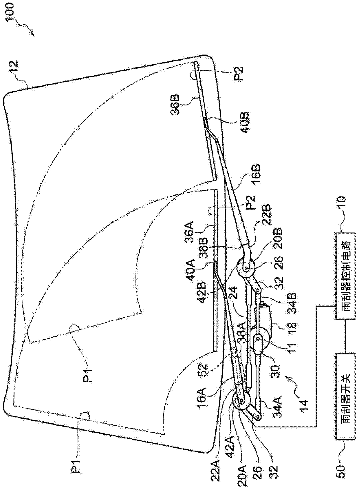
[0041] figure 1 It is a schematic diagram showing the structure of the wiper device 100 according to the embodiment of the present invention. The wiper device 100 is used to wipe the windshield 12 included in a vehicle such as a passenger car with the wiper blades 36A, 36B.

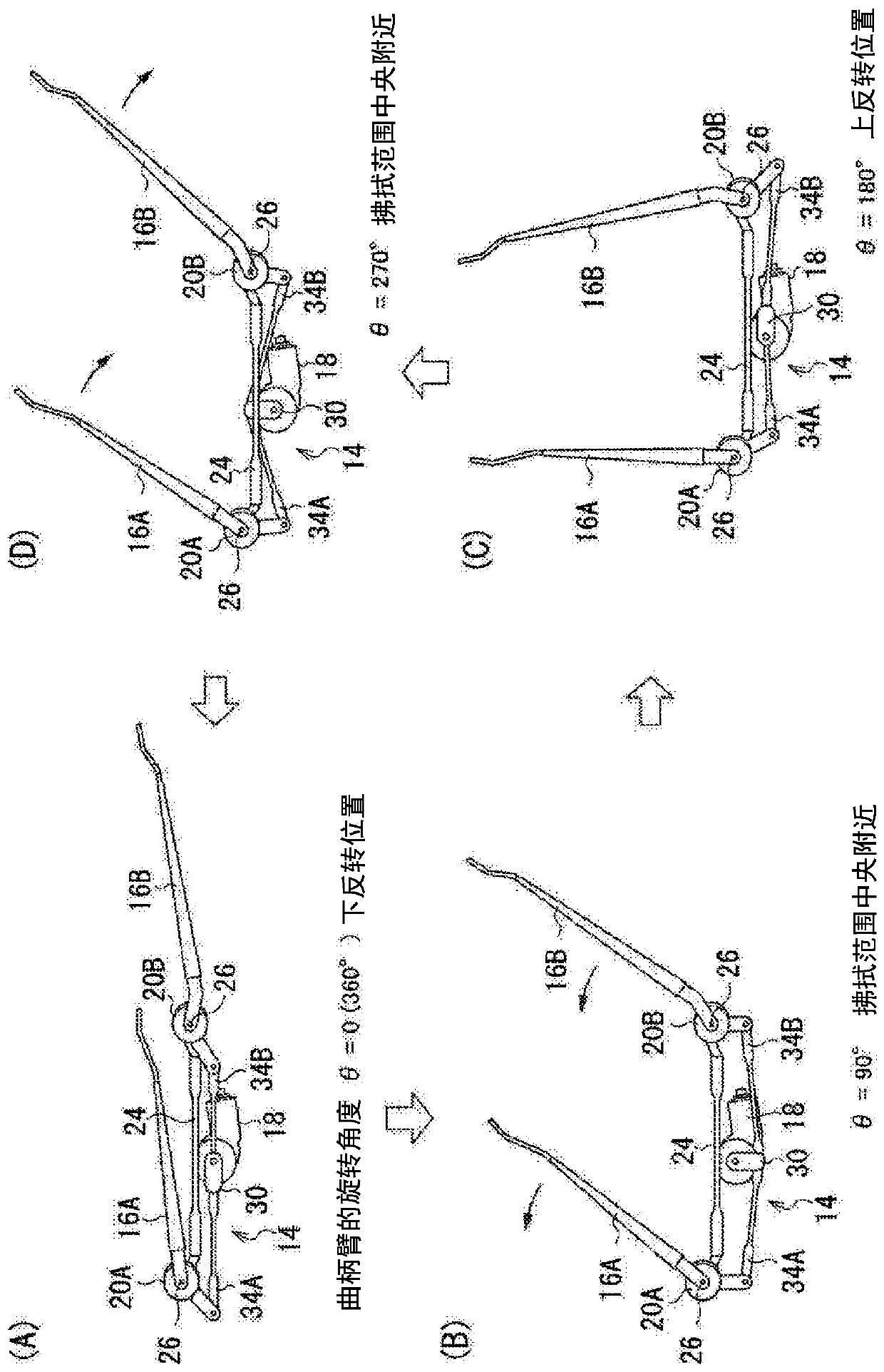
[0042]As shown in this figure, the wiper device 100 includes: a wiper motor 18, which drives an unillustrated rotating shaft to rotate, and drives the output shaft 11 to rotate through an unillustrated reduction mechanism composed of a worm gear and the like; a link mechanism 14, whose Converts rotational drive of the output shaft 11 into reciprocating movement of two links 34A, 34B described later; and two wiper arms 16A, 16B at the rotating shaft 26 that rotates in conjunction with the reciprocating movement of the links 34A, 34B The bases 42A, 42B are connected to swing by the rotation of the rotating shaft 26, so that the wiper blades 36A, 36B respectively connected to the front ends 40A, 40B are pos...


PUM


Abstract

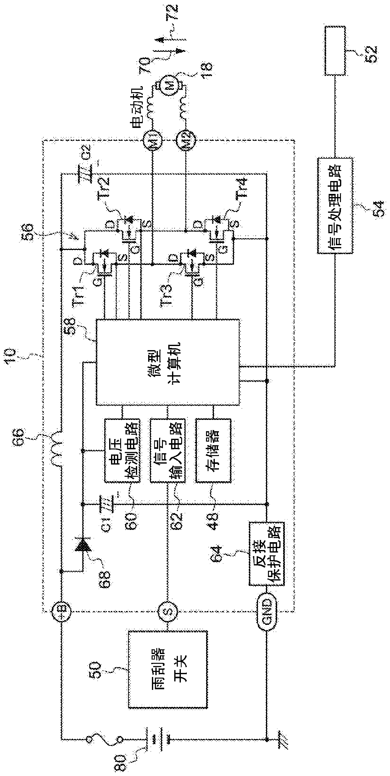
A windshield wiper device includes: a wiper arm which has a recess, is swung according to the rotation of a wiper motor, and allows a wiper blade coupled to the leading end thereof to wipe clean the surface of a windshield; an acceleration sensor which is mounted in the recess of the wiper arm; a drive circuit which generates a voltage to be applied to the wiper motor; and a control circuit whichcontrols the drive circuit so that a voltage which decreases the change in the acceleration of the wiper arm detected by the acceleration sensor is applied to the wiper motor.

Description

technical field [0001] The invention relates to a wiper device. Background technique [0002] In the wiper device that wipes the windshield with the wiper blade, small incremental vibrations of the wiper blade during the wiping operation, so-called chattering, may occur due to fluctuations in the frictional load on the glass surface or fluctuations in the voltage of the battery, which is the power source. Condition. [0003] Chattering not only hinders the wiping of the windshield surface but is also an uncomfortable phenomenon for the occupants of the vehicle, and therefore it is desired to avoid occurrence of the vibration as much as possible in the wiper device. In the past, chatter vibration was suppressed or eliminated by repeated trial and error such as adding corresponding parts and adjusting the actual machine, or increasing the voltage applied to the wiper motor to increase the wiping speed. [0004] However, in the above-mentioned trial and error, there are probl...

Claims


Application Information

Patent Timeline
Patent Type & Authority Applications(China)
IPC IPC(8): B60S1/08
CPCB60S1/08B60S1/0859B60S1/245B60S1/3429B60S1/0807B60S1/0822B60S1/28B60S1/3425
Inventor 岩崎雄太配岛拓司小笠原皓哉富田充祥早川夏人
Owner DENSO CORP
Learn More