An Omnidirectional Inductive Obstacle Avoidance Mechanism for Chassis

A chassis and swing plate technology, applied in the field of robot navigation, can solve problems such as increased difficulty in layout, complicated circuit wiring, and the impact of robot obstacle avoidance, and achieve the effect of simple and compact structure and increased volume

Active Publication Date: 2021-12-28
SHENYANG SIASUN ROBOT & AUTOMATION
View PDF0 Cites 0 Cited by
  • Summary
  • Abstract
  • Description
  • Claims
  • Application Information

AI Technical Summary

Problems solved by technology

The above two common mechanical collision sensors obtain a single IO signal after being triggered, and cannot know exactly which angle the obstacle is at.
An improved method is to arrange N sensors in multiple sections, so that N areas can be identified, and at the same time, the number of signal sources should also be changed to N. As the accuracy of identifying angles increases, the number of sensors will also increase, but it will also As a result, the layout is more difficult, and the circuit wiring is more and more complicated.
[0006] In addition, if the robot’s collision point information is not accurate enough, it will have a great impact on the obstacle avoidance of the robot’s movement, and it is easy to cause the robot to back up and hit it again, or to go around a particularly large redundant angle.

Method used


Image

  • An Omnidirectional Inductive Obstacle Avoidance Mechanism for Chassis
  • An Omnidirectional Inductive Obstacle Avoidance Mechanism for Chassis
  • An Omnidirectional Inductive Obstacle Avoidance Mechanism for Chassis

Examples


Embodiment Construction

[0025] The present invention will be described in further detail below in conjunction with the accompanying drawings.

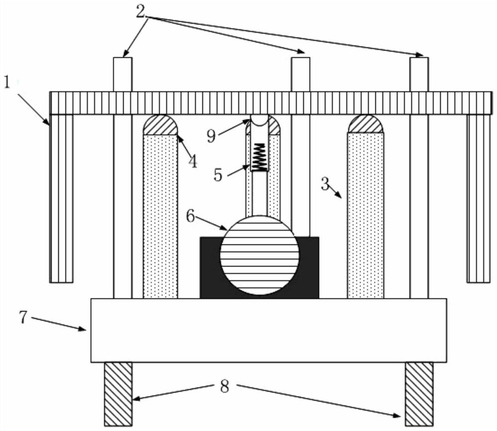
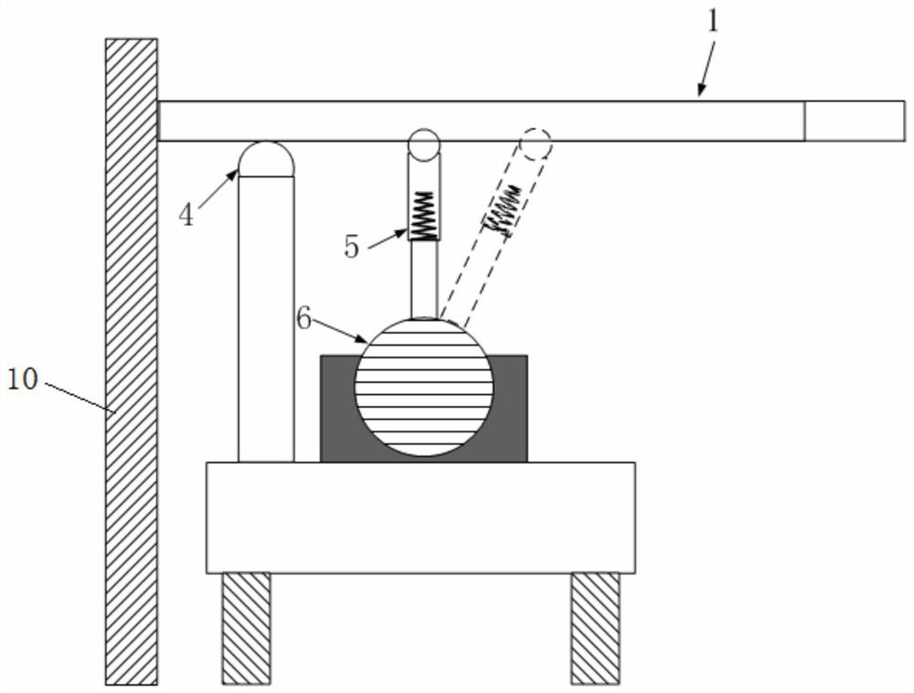
[0026] Such as Figure 1~4 As shown, the present invention includes a swing plate 1, a Hall sensor 6, an elastic telescopic rod 5 and a chassis 7, wherein the chassis 7 is a robot chassis, and a swing plate support column 3 is provided on the chassis 7, and the swing plate 1 is placed On the support column 3 of the oscillating disk, the Hall sensor 6 is rotatably arranged in the middle of the upper side of the chassis 7. One end of the elastic telescopic rod 5 is fixedly connected to the Hall sensor 6, and the other end is connected to the lower side of the oscillating disk 1. The middle part is hinged, and the elastic telescopic rod 5 rotates and stretches along with the movement of the oscillating plate 1 .

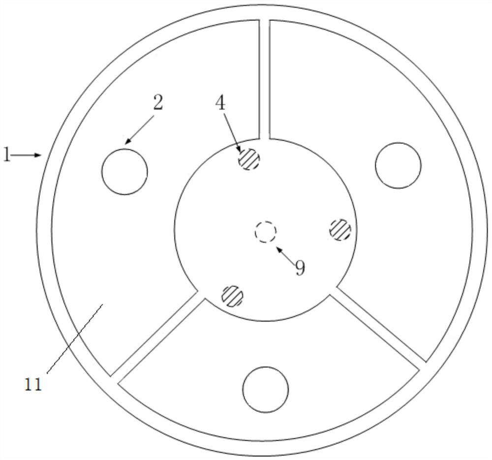
[0027] Such as Figure 1~3 As shown, in this embodiment, three oscillating disk support columns 3 are evenly distributed along the circumferential d...


PUM


Abstract

The invention relates to the technical field of robot navigation, in particular to an omnidirectional induction obstacle avoidance mechanism for a chassis, which includes a swing plate, a Hall sensor, an elastic telescopic rod and a chassis, wherein a swing plate support column is arranged on the chassis, so The oscillating plate is placed on the support column of the oscillating plate, and the Hall sensor is rotatably arranged in the upper middle part of the chassis. One end of the elastic telescopic rod is fixedly connected to the Hall sensor, and the other end is hinged to the lower middle part of the oscillating plate. , and the elastic telescopic rod rotates and expands with the movement of the oscillating plate. The invention can fully obtain the precise collision angle of the obstacle, and greatly improves the obstacle avoidance efficiency of the robot during navigation.

Description

technical field [0001] The invention relates to the technical field of robot navigation, in particular to an omnidirectional induction obstacle avoidance mechanism for a chassis. Background technique [0002] With the rapid development of automation technology, various robots have gradually been extended to enterprise production and residents' lives. Among them, mobile robots use multiple sensors to feed back data, and can move with ease and complete tasks in a changeable and complex environment. [0003] Mobile robots in the prior art mainly rely on laser or vision as the information source for navigation, but both laser and vision have detection "dead spots". For example, if there is a black obstacle in a black place, it is difficult for vision technology to identify it. In terms of laser, the 2D laser can only scan one plane. The downward scanning angle of the existing fixed 3D laser generally does not exceed 35 degrees, which makes the robot unable to see the situation u...

Claims


Application Information

Patent Timeline
Patent Type & Authority Patents(China)
IPC IPC(8): G05D1/02
CPCG05D1/0276
Inventor 姜铁程刘鑫旭李健吴树智于浩狄
Owner SHENYANG SIASUN ROBOT & AUTOMATION
Why Eureka
Try Eureka