
Room temperature-control ventilating system and control method thereof

A ventilation system and control system technology, which is applied in space heating and ventilation control input, heating and ventilation control system, heating and ventilation safety system, etc. It can solve the problems of large equipment, many processing units, and inability to realize dehumidification function

Active Publication Date: 2019-07-02
CHONGQING UNIV
View PDF16 Cites 12 Cited by
  • Summary
  • Abstract
  • Description
  • Claims
  • Application Information

AI Technical Summary

Problems solved by technology

[0004] Application number CN201410058724.1, the patent document titled "room temperature control ventilation system and its application", discloses a room temperature control ventilation system, which realizes functions such as linkage air conditioning, energy saving, cooling, ventilation, and air purification. Dehumidification function
Another example is the application number CN201611172058.X, in the patent document titled "A Room Temperature Control Ventilation System", which discloses a room temperature control ventilation system, which integrates fresh air heat exchange, internal circulation constant temperature dehumidification, dehumidification refrigeration, heating and Air filtration and other functions, but all rotating equipment including compressors are placed in a box, the air duct is relatively tortuous, there are many processing units in the equipment, the equipment is large in size, vibration and noise are large

Method used


Image

  • Room temperature-control ventilating system and control method thereof
  • Room temperature-control ventilating system and control method thereof
  • Room temperature-control ventilating system and control method thereof

Examples


specific Embodiment approach

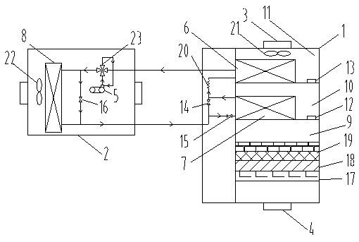
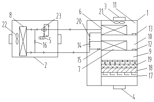
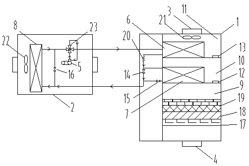
[0057] Specific implementation method: a room temperature control ventilation system, the hardware part structure see figure 1, including an indoor box 1 installed indoors and an outdoor box 2 installed outdoors, one end of the inner cavity of the indoor box 1 is provided with an air inlet interface 4 for air intake, and the other end is provided with an air supply interface for air supply 3. The inner cavity of the indoor box is provided with a filter structure near the air inlet interface, and an indoor heat exchanger is installed between the filter structure and the air supply interface; an outdoor heat exchanger 8 is installed in the inner cavity of the outdoor box, and the outdoor heat exchanger The heat exchange medium interface between the heat exchanger 8 and the indoor heat exchanger is connected with a first heat exchange medium pipeline and a second heat exchange medium pipeline, and a compressor 5 and a heat exchange medium pipeline are installed on the first heat e...


PUM


Abstract

The invention discloses a room temperature control ventilating system. The room temperature control ventilating system comprises an indoor box body mounted in an indoor space, and an outdoor box bodymounted in an outdoor space; a filtering structure is arranged on the position, close to an air inlet connector, of an inner cavity of the indoor box body, and an indoor heat exchanger is mounted between the filtering structure and the air feeding connector; an outdoor heat exchanger is mounted in an inner cavity of the outdoor box body, and a first heat exchanging medium pipeline and a second heat exchanging medium pipeline are arranged on a heat exchanging medium connector between the outdoor heat exchanger and the indoor heat exchanger in a connected mode to constitute a circulating heat exchanging system; and the room temperature control ventilating system is characterized in that the indoor heat exchanger comprises a first indoor heat exchanger body and a second indoor heat exchangerbody which are arranged in a spaced mode and can be switched to achieve four operating modes, and the indoor heat exchanger further comprises a control system. The various ventilating temperature control modes can be provided and can be subjected to switching control conveniently according to needs, and the ventilating function and the user experience are improved.

Description

technical field [0001] The invention relates to the technical field of building room ventilation, in particular to a room temperature control ventilation system and a control method thereof. Background technique [0002] In recent years, with the unprecedented expansion of single buildings, the increasing airtightness of buildings, and the increasingly serious environmental pollution, the traditional natural ventilation methods can no longer meet the health and comfort needs of the human body for fresh air. In addition, if the humidity in the living environment is too high, it will It can cause insomnia and dreaminess. At the same time, a large number of bacteria are easy to breed in a humid environment. In addition, furniture and clothing are prone to mold and odor. Some fungi are easy to attach to dust, which may cause illness. [0003] However, the air treatment equipment currently on the market has a single function, and few of them have the function of fresh air dehumid...

Claims


Application Information

Patent Timeline
Patent Type & Authority Applications(China)
IPC IPC(8): F24F1/0035F24F11/64F24F11/61F24F11/65F24F11/72F24F110/12F24F110/20
CPCF24F1/0007F24F11/61F24F11/64F24F11/65F24F11/72F24F2110/12F24F2110/20
Inventor 陈金华杨璨赖诗璇郑洁
Owner CHONGQING UNIV
Learn More