pneumatic tire

A technology of pneumatic tires and tires, which is applied to off-road vehicle tires, tire parts, tire treads/tread patterns, etc., can solve problems such as weakening rigidity, and achieve the effect of improving decorative effect and maintaining traction effect.

Active Publication Date: 2021-07-09
TOYO TIRE & RUBBER CO LTD
View PDF8 Cites 0 Cited by
  • Summary
  • Abstract
  • Description
  • Claims
  • Application Information

AI Technical Summary

Problems solved by technology

Regarding the tire having such an annular rib, the inventors of the present invention have found that the rigidity of the annular rib is weakened in the lug grooves that define the buttress blocks. There is room for improving the protection effect
In addition, it was also found that sometimes it is considered that the buttress pattern block is divided by the annular rib as the dividing line, which also has room for improvement in terms of decorative effect

Method used


Image

  • pneumatic tire
  • pneumatic tire
  • pneumatic tire

Examples


Embodiment Construction

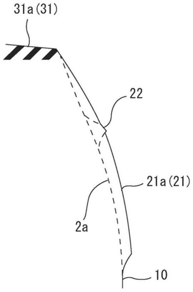
[0028] Hereinafter, the first embodiment of the present invention will be described with reference to the drawings. figure 1 Summary represents a half-cross-sectional view of a tire sub-line semi-cross-sectional view of 1 example of the pneumatic tire according to the present invention, which is equivalent to figure 2 A-a section. figure 2 It is a deployment diagram showing the shoulder area and the wall region of the pneumatic tire. in figure 2 In the left and right directions, the tire circumferential direction is performed in the lower direction of the tire width direction, and the inner direction is inside the tire width direction. Figure 3A ~ 3D It is expressed separately figure 2 A schematic view of the A-A, B-B, C-C, D-D section.

[0029] The inflatable tire T is a non-paving pavement of a non-paving pavement in a harsh pavement including a muddy location or a rock field. Such as figure 1 As shown, the pneumatic tire T is provided: a pair of bead portion 1, from each of the...


PUM


Abstract

Provided is a pneumatic tire capable of improving the protective effect and decorative effect of buttress areas. The pneumatic tire is provided with a plurality of lug grooves (8) extending from the shoulder area (3S) of the tread portion (3) toward the outside in the tire width direction and reaching the buttress area (2B) of the sidewall portion (2). ; and pattern blocks, which are divided by a plurality of horizontal grooves (8). The pattern blocks divided by a plurality of horizontal grooves (8) include: the shoulder block (31) arranged in the shoulder area (3S), and the buttress block (31) arranged in the buttress area (2B) twenty one). The buttress region (2B) is provided with an annular rib (22) that cuts across the buttress block (21) and extends annularly along the tire circumferential direction. At least some of the lug grooves (8A) among the plurality of lug grooves (8) are provided with widened portions (23) to increase the width of the annular rib (22).

Description

Technical field [0001] The present invention is directed to an avelation of a pneumatic tire that travels on a harsh road such as a muddy segment or a rock field. Background technique [0002] It is well known that such a pneumatic tire is to improve the travelability of the harsh pavement such as a muddy segment or rock field, and a plurality of wall blocks are arranged in the helper side of the sidewall. According to the tires including such a wall block, since it is possible to obtain the effect (traction effect) of the traction caused by shear resistance in the case of traveling on the harsh road, therefore, the harsh pavement can be improved. Further, it is possible to obtain: the outer surface of the side portion away from the surface of the rock surface (protective effect) can be improved (protective effect), thereby improving the abutment resistance. Further, it is also possible to obtain a decorative effect (appearance decoration effect) brought by the uneven shape of th...

Claims


Application Information

Patent Timeline
Patent Type & Authority Patents(China)
IPC IPC(8): B60C11/03B60C11/01B60C13/00
CPCB60C11/03B60C11/01B60C13/00B60C13/02B60C2200/14B60C11/1236B60C11/1369B60C11/0327B60C11/11B60C2011/013B60C2011/0358B60C2011/1213B60C2011/1254B60C11/1204
Inventor 桒野慎吾
Owner TOYO TIRE & RUBBER CO LTD
Why Eureka
Try Eureka