A corner splint positioning and tensioning device

A technology of tensioning device and splint, which is applied to the device for coating liquid on the surface, pretreatment surface, coating, etc., can solve the problem that the position of the grabbing ring is not fixed, cannot adapt to various specifications, and position the tensioning device Problems such as easy deformation, to achieve the effects of labor-saving and convenient pressing and loosening operations, easy automation of operations, and improvement of operating efficiency

Active Publication Date: 2020-06-19
SHANGHAI JIAOTONG UNIV +2
View PDF4 Cites 0 Cited by
  • Summary
  • Abstract
  • Description
  • Claims
  • Application Information

AI Technical Summary

Problems solved by technology

This method has the following problems: 1. The method of manual fastening of the rubber belt cannot ensure that the corner splint is evenly stressed, the tension of the rubber belt is limited, and the force cannot be accurately controlled, resulting in substandard bonding strength and assembly accuracy. The waste rate is higher and the production cost is higher; 2. The existing method does not consider the control of the mutual position of the plywood and the polyurethane board, resulting in the relative displacement of the multi-layer board of the insulation box during the handling or curing process, making it necessary to retain more in the early stage. There is a lot of machining allowance, and more complex machining is required in the later stage to ensure the yield rate, the production efficiency is low, and the production cost is high; 3. The existing method is time-consuming, laborious, and low in production efficiency, and is not suitable for large-scale industrial production
[0004] (1) The metal corner frame and the elastic part are not rigidly connected, which leads to the easy deformation of the positioning tensioning device, so that the assembly deviation of the corner splint cannot be accurately corrected, which affects the assembly accuracy. At the same time, due to the deformation, the position of the grabbing ring is not fixed. Unable to realize fully automatic operation of manipulator
[0005] (2) When the device is manually disassembled, four people are required to pull it from four directions at the same time, which consumes manpower, and due to the limitation of manpower, the force of the spring cannot be greatly increased, so that the pressing force is limited and the bonding strength of the corner splint cannot be satisfied. requirements
In addition, due to the possible presence of residual glue on the corner cleats, the positioning tensioner is bonded to the corner cleats, increasing the difficulty of removal
[0006] (3) After the device is removed from the insulating box, it cannot be stacked tightly and neatly, which increases the space and time required for logistics turnover, and it is difficult to realize fully automated access operations
However, this device cannot adapt to many different specifications, which increases the difficulty in the pairing management of the tensioning device and the insulating box

Method used


Image

  • A corner splint positioning and tensioning device
  • A corner splint positioning and tensioning device
  • A corner splint positioning and tensioning device

Examples


Embodiment 1

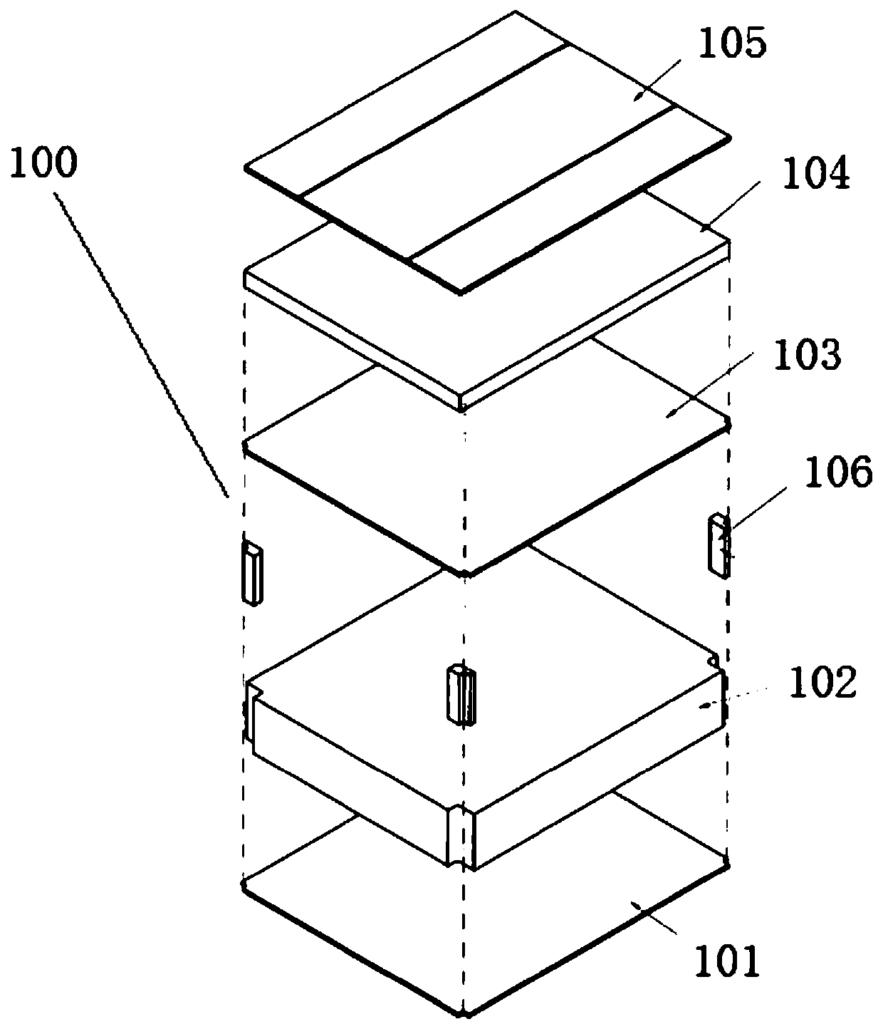
[0063] In order to achieve the figure 1 For the fixation of the insulating box 100 shown in the curing stage after gluing, this embodiment proposes a corner splint positioning and tensioning device. The insulating box 100 has a five-layer structure, including No. 2 board 102 (i.e. the substrate), and No. 1 board 101, No. 3 board 103, No. 4 board 104 and No. 5 board 105 bonded on the upper and lower surfaces of No. 2 board 102, Wherein, the four corners of No. 2 board 102 are provided with the first concave right-angle groove perpendicular to its upper and lower surfaces, and a corner splint 106 is bonded in the first concave right-angle groove, and the outside of this corner splint 106 has The concave right-angle groove is parallel to the second concave right-angle groove.

[0064] see image 3 As shown, the positioning and tensioning device of this embodiment includes an outer frame 200 whose inner dimension is not smaller than the profile size of the side of the insulating...

Embodiment 2

[0070] like Figure 5 As shown, the insulating box of the LNG ship is fixedly installed. The structure of the tensioning device of this embodiment is the same as that of Embodiment 1, without the handle 320 lever structure. The difference is that the insulating box 100 in this embodiment has only a three-layer structure, without the second layer of the insulating box 100 and without the fifth board 105 . Similarly, the positioning and tensioning device is divided into two layers, wherein, the limit bar 308 protruding upwards from the pressure roller 306 of the lower positioning and tensioning device is provided with a limit baffle 307, and on the pressure roller 306 of the upper positioning and tensioning device, there is There is no limit baffle 307 .

Embodiment 3

[0072] see Figure 6 , the insulation box 100 is only a three-layer structure, without the second layer of the insulation box 100, and without the fifth board 105. Different from the above-mentioned embodiment 1, in this embodiment, the installation between the pressure roller 306 and the first connecting plate 305 is carried out in the following manner:

[0073] see Figure 7-Figure 9 As shown, the first connecting plate 305 is also provided with a push rod hole 312 that runs through and is parallel to the guide column 321, and a push rod 315 with an inner diameter smaller than the hole diameter and whose end is connected to the pressure roller 306 is perforated in the push rod hole 312. The first connecting plate 305 is also rotatably mounted on the push rod shaft 313 parallel to the second concave right-angle groove and fixedly connected to the push rod 315 . The push rod 315 can swing within a certain range in the push rod hole 312, so that the pressure roller 306 can au...


PUM


Abstract

The invention relates to a locating tensioning device of a corner clamping plate used for fixing an insulating tank in the curing stage after gluing. The locating tensioning device comprises an outerframe with inner side size larger than or equal to the side surface outline size of the insulating tank, and angle frames arranged at four corners of the outer frame, the angle frames comprises bottomplates fixed to the end angles of the outer frame, bases mounted on the bottom plates, guiding columns slidably penetrating through the bases, first connecting plates and second connecting plates correspondingly and fixedly mounted at the inner ends and the outer ends of the guiding columns, compression rollers arranged on the inner sides of the first connecting plates and used for being attachedagainst second concave right angle grooves, and compression springs sleeving the guiding columns, and the two ends of the compression springs abut against the first connecting plates and the base. Compared with the prior art, the assembling quality and the efficiency of the corner clamping plate can be improved through the locating tensioning device, mounting and disassembling operation are morerelaxed and can be operated by one person, in addition, the locating tensioning device can be piled up tidily in high density, full-automatic operation is convenient to achieved, and the logistic turnover efficiency is improved.

Description

technical field [0001] The invention belongs to the technical field of LNG ship insulation box production, and relates to a corner splint positioning and tensioning device. Background technique [0002] Part of the box type of the LNG marine insulation box adopts a sandwich structure of plywood→polyurethane board→plywood bonded layer by layer, and the four corners need to be bonded with corner splints. For special working conditions such as turbulence and low temperature at sea, this kind of box has strict requirements on bonding strength and assembly accuracy. At present, the assembly of the corner splints at home and abroad is manual operation, and the fixation after glue application is manually fastened with rubber belts and followed by the aging planning process. This method has the following problems: 1. The method of manual fastening of the rubber belt cannot ensure that the corner splint is evenly stressed, the tension of the rubber belt is limited, and the force can...

Claims


Application Information

Patent Timeline
Patent Type & Authority Patents(China)
IPC IPC(8): B05D3/00
CPCB05D3/007
Inventor 蒋知峰孔谅梁诚周春立冯炜杰张悦张立中张跃龙曹恒
Owner SHANGHAI JIAOTONG UNIV
Why Eureka
Try Eureka