
High-temperature denitration and dust removal integration equipment

A technology for denitrification and dust removal and equipment, applied in the field of flue gas purification, can solve the problems of increased flue resistance, too high, and limited dust removal effect, so as to improve the overall denitrification and dust removal efficiency, reduce wear and blockage, and have little influence on flue gas flow Effect

Active Publication Date: 2019-07-02
CPI YUANDA ENVIRONMENTAL PROTECTION ENG
View PDF9 Cites 2 Cited by
  • Summary
  • Abstract
  • Description
  • Claims
  • Application Information

AI Technical Summary

Problems solved by technology

[0002] With the introduction of the national coal-fired ultra-low emission policy, it is difficult for the existing desulfurization and dust removal technologies to meet the strict emission indicators under the ultra-low emission requirements.
[0003] In the flue gas denitration system of SCR selective catalytic reduction technology in the prior art, high-temperature dust removal is mainly based on inertia and gravity deposition, but this kind of high-temperature dust removal device does not have simultaneous denitrification effect, which increases the flue resistance and affects the stability of flue gas flow Sexuality, increase the cost of denitrification system operation, due to the high flue gas flow rate in the actual use process, the dust removal effect is limited

Method used


Image

  • High-temperature denitration and dust removal integration equipment
  • High-temperature denitration and dust removal integration equipment
  • High-temperature denitration and dust removal integration equipment

Examples


Embodiment Construction

[0032] In order to make the purpose, technical solutions and advantages of the embodiments of the present invention more clear, the following will clearly and completely describe the technical solutions of the embodiments of the present invention in conjunction with the drawings of the embodiments of the present invention. Apparently, the described embodiments are some, not all, embodiments of the present invention. All other embodiments obtained by those skilled in the art based on the described embodiments of the present invention belong to the protection scope of the present invention.

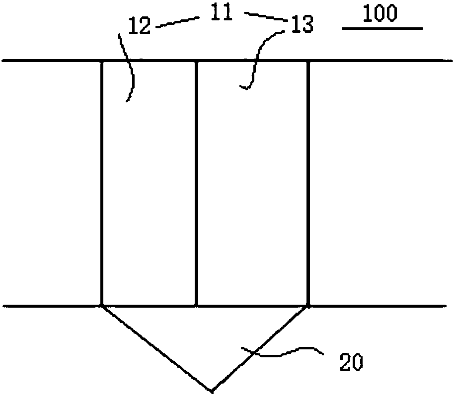
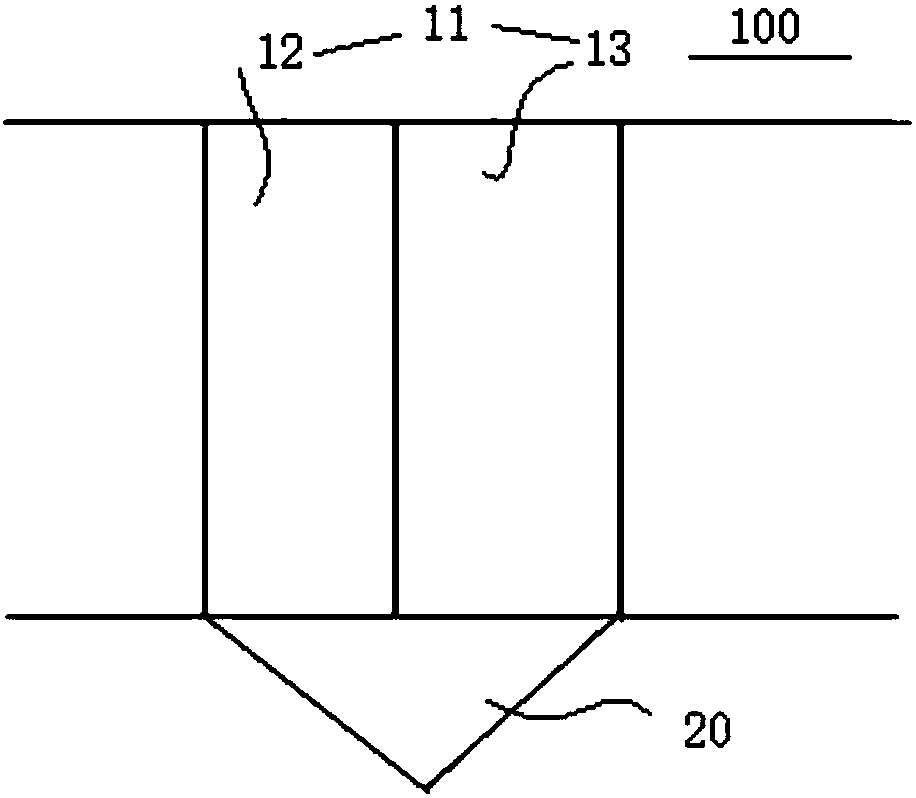
[0033] The high-temperature denitrification and dust removal integrated equipment 100 according to the embodiment of the present invention will be described in detail below with reference to the accompanying drawings.

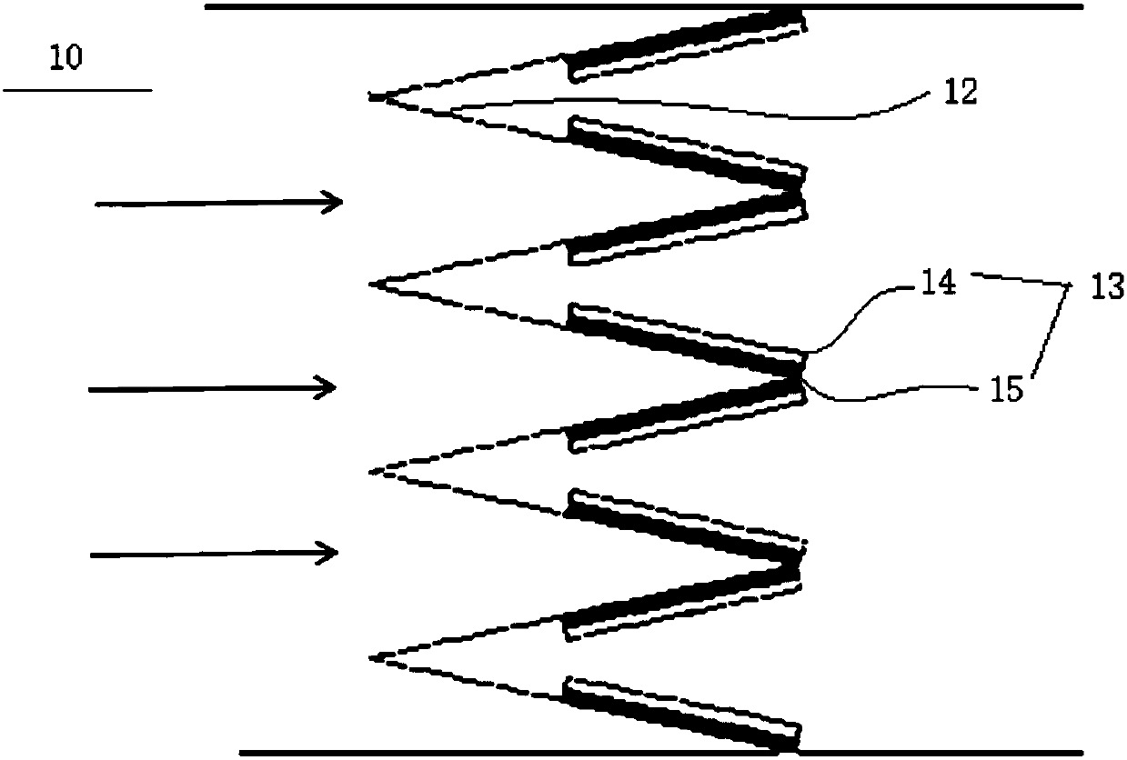
[0034] Such as figure 1 As shown, the high-temperature denitrification and dust removal integrated equipment 100 according to the embodiment of the present invention includ...


PUM

PropertyMeasurementUnit
angleaaaaaaaaaa

Abstract

The invention provides high-temperature denitration and dust removal integration equipment. The high-temperature denitration and dust removal integration equipment comprises a body and an ash bucket,wherein the body is of a V-shaped plate-type structure; the body is arranged in a flue or a reactor and is used for carrying out out denitration and dust removal on flowing-through flue gas; and the ash bucket is arranged outside the flue or the reactor, is located under the body and is used for collecting dust removed by the body. According to the high-temperature denitration and dust removal integration equipment provided by the embodiment of the invention, the V-shaped plate-type body is arranged in the flue or the reactor to remove the dust in the flue or the reactor and is used for cooperatively removing nitrogen oxide; the ash bucket for collecting the dust is arranged under the body; the high-temperature denitration and dust removal integration equipment has small pressure loss andsmall influences on the flowing of the flue gas, and can be used for effectively removing the nitrogen oxide in fly ash and the flue gas at high temperature, so that the abrasion to a catalyst and theblocking to subsequent equipment, which are caused by the fly ash in an SCR (Selective Catalytic Reduction) system can be effectively reduced and the total denitration efficiency of an SCR denitration system is improved.

Description

technical field [0001] The invention relates to the field of flue gas purification, and more specifically, to a high-temperature denitrification and dust removal integrated equipment. Background technique [0002] With the introduction of the national coal-fired ultra-low emission policy, it is difficult for the existing desulfurization and dust removal technologies to meet the strict emission targets under the ultra-low emission requirements. [0003] In the flue gas denitration system of SCR selective catalytic reduction technology in the prior art, high-temperature dust removal is mainly based on inertia and gravity deposition, but this kind of high-temperature dust removal device does not have simultaneous denitrification effect, which increases the flue resistance and affects the stability of flue gas flow Sexuality, increase the cost of denitrification system operation, due to the high flue gas flow rate in the actual use process, the dust removal effect is limited. T...

Claims


Application Information

Patent Timeline
Patent Type & Authority Applications(China)
IPC IPC(8): B01D45/08B01D45/18B01D53/90B01D53/56
CPCB01D45/08B01D45/18B01D53/8631B01D53/90B01D53/56B01D53/86
Inventor 聂华吴其荣喻江涛刘宇吉庆范振兴黎方潜周川王进周川雄
Owner CPI YUANDA ENVIRONMENTAL PROTECTION ENG
Learn More