
A business entity implementation method and system based on domain-driven design

A technology of domain-driven design and business entities, applied in domain-driven design-based business entity implementation methods and system fields, can solve the problems of irresponsibility of data presentation style, irresponsibility of logical data and user data correctness, etc., to achieve improvement Program performance, improving operating efficiency, and improving overall efficiency

Active Publication Date: 2019-06-28
INSPUR COMMON SOFTWARE
View PDF4 Cites 8 Cited by
  • Summary
  • Abstract
  • Description
  • Claims
  • Application Information

AI Technical Summary

Problems solved by technology

Responsible for the correctness and validity of the input logical data, but not responsible for the correctness of the output logical data and user data, and not responsible for the presentation style of the data

Method used


Image

  • A business entity implementation method and system based on domain-driven design
  • A business entity implementation method and system based on domain-driven design
  • A business entity implementation method and system based on domain-driven design

Examples


Embodiment 1

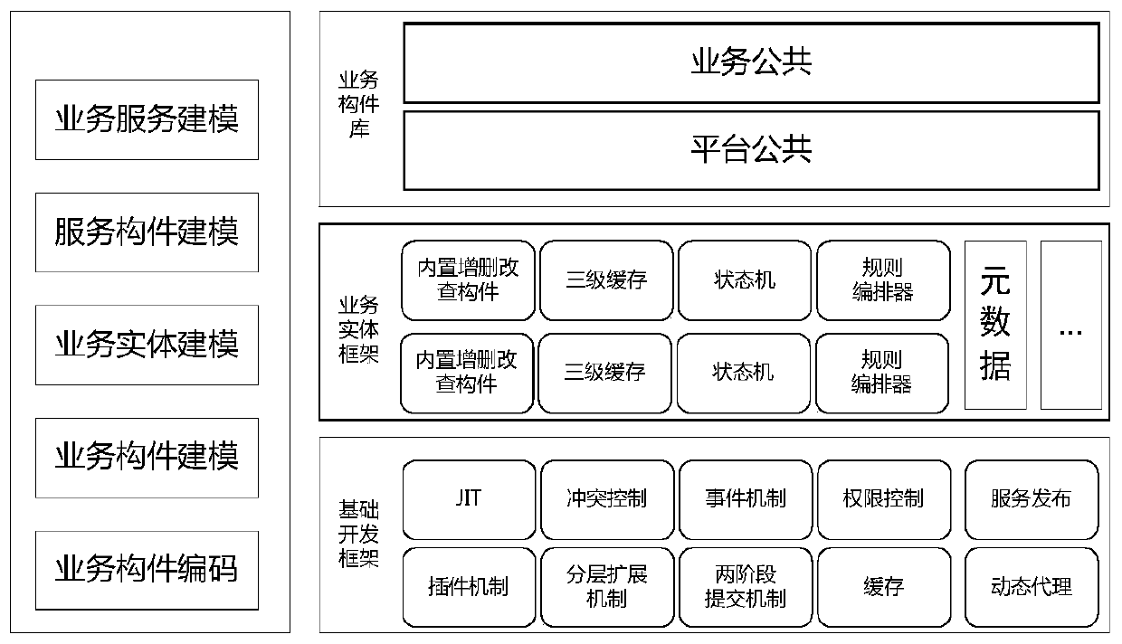
[0076] as attached figure 1 As shown, the method for implementing a business entity based on domain-driven design of the present invention has the following steps:

[0077] S1. Establish a business entity model through a business entity modeling tool: the business entity model adopts the entity model abstracted from the domain-driven design to describe the business logic; the business entity model includes two parts: the entity data structure and the business logic layer;

[0078] Wherein, the entity data structure includes a root entity and several sub-entities (there may be no sub-entities);

[0079] Entities include several attributes, set the data type of the attribute or set the attribute as an enumeration type or an associated type; among them, the data type includes basic types of characters, text, time, date, Boolean, integer, floating-point numbers, and binary types; association Type refers to the association of the main sub-entity and the association of the current ...

Embodiment 2

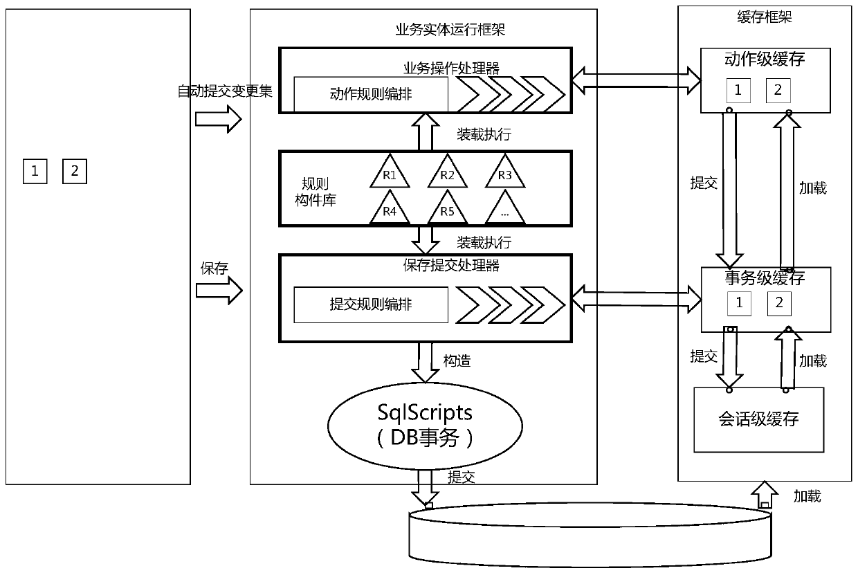
[0117] The business entity system based on domain-driven design of the present invention includes a business entity model, a business entity operation module, a cache module, an incremental mechanism module, a business logic layer, a business entity designer, and a JIT generator; a business entity model, a business The entity model is used to describe the business logic, which is abstracted by domain-driven design; the business entity model includes two parts: the entity data structure and the business logic layer; the business entity operation module is used to provide the basic framework for the operation of the business logic, and the operation of the business entity The module includes the most basic content of the business logic layer, encapsulates the public business logic to realize the expansion mechanism, and the business function is based on this framework plus custom business logic code; cache module, the cache module includes session-level cache layer, transaction-le...


PUM


Abstract

The invention discloses a business entity implementation method and system based on domain-driven design, belonging to the application development field. The technical problem to be solved by the invention is how to provide a unified framework for domain core business logic development. According to the technical scheme, the business entity implementation method based on domain drive design comprises the following steps that S1, establishing a business entity model through a business entity modeling tool; S2, establishing a service entity running framework; S3, establishing a cache framework in the service entity running framework; S4, establishing an increment mechanism in a business entity operation framework; S5, splitting the business logic into an entity logic layer and a service logic layer; S6, establishing a service entity designer; and S7, establishing a JIT generator. The invention further discloses a service entity system based on the domain drive design.

Description

technical field [0001] The invention belongs to the field of application program development and relates to the development of the core business logic layer of the field, in particular to a business entity realization method and system based on domain-driven design. Background technique [0002] With the development of more and more application programs, due to the lack of a unified framework and lack of constraint capabilities due to the development of core business logic in the domain, the development of the domain layer is relatively loose, requiring high levels of developers and developing applications in stability and It is relatively weak to adapt to the changes of the front-end UI, which is not conducive to the stability of the business logic layer code. [0003] Business Logic Layer (Business Logic Layer) is undoubtedly the part that embodies the core value in the system architecture. Its focus is mainly on system design related to business requirements, such as the...

Claims


Application Information

Patent Timeline
Patent Type & Authority Applications(China)
IPC IPC(8): G06F8/35G06F8/38
Inventor 宫保金孙立新张进周由甲王洁
Owner INSPUR COMMON SOFTWARE
Learn More