
Cross-interval digital measurement method, device and system based on network sampling absolute delay compensation

A technology of delay compensation and network sampling, which is applied in measurement devices, time division multiplexing systems, and measurement of electrical variables. High, improve the accuracy, improve the effect of interpolation accuracy

Active Publication Date: 2019-06-28
江苏凌创电气自动化股份有限公司
View PDF10 Cites 7 Cited by
  • Summary
  • Abstract
  • Description
  • Claims
  • Application Information

AI Technical Summary

Problems solved by technology

It can be seen that the inter-interval digital energy meter completely depends on the synchronous clock of the whole station as its only clock source. Once the synchronous clock loses the merging unit, it will run out of synchronization, while the inter-interval electric energy meter can only be processed according to the out-of-synchronization, or ignore it. Continue to measure but mark the out-of-step sign, or stop measuring and give an alarm, but neither of these two methods can solve the problem of digital metering reliability
[0004] Therefore, at the current stage, there is an urgent need for a measurement method without changing the system architecture. Under the existing digital measurement system architecture, the digital measurement can use the absolute delay to perform digital sampling by measuring the precise delay of the network. Delay compensation to solve the shortcomings of digital metering that cannot work in the case of out-of-step

Method used


Image

  • Cross-interval digital measurement method, device and system based on network sampling absolute delay compensation
  • Cross-interval digital measurement method, device and system based on network sampling absolute delay compensation
  • Cross-interval digital measurement method, device and system based on network sampling absolute delay compensation

Examples


Embodiment Construction

[0053] The present invention will be further described below in conjunction with the accompanying drawings. The following examples are only used to illustrate the technical solution of the present invention more clearly, but not to limit the protection scope of the present invention.

[0054] A cross-interval digital measurement method based on network sampling absolute delay compensation, including:

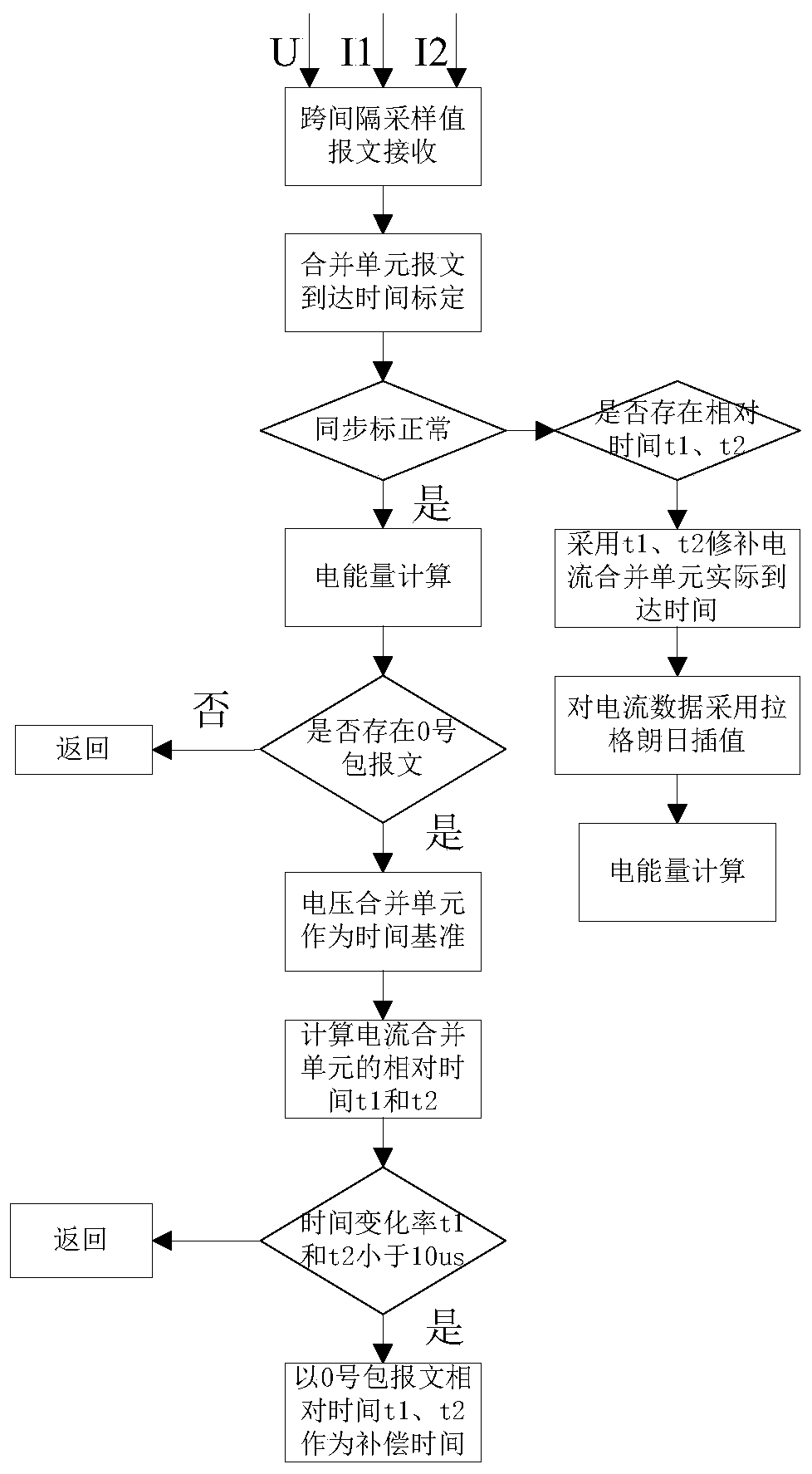
[0055] Based on the actual arrival time of the voltage sampling data value in any message in any sampling cycle that meets the preset conditions when the synchronization is normal, the relative time of the two current sampling data values ​​in the current message is calculated respectively, and the The above relative time is used as the compensation time.

[0056] According to the compensation time, the synchronous interpolation time corresponding to each current sampling data value in the following consecutive messages is calculated respectively in any sampling period when the...


PUM


Abstract

The invention discloses a cross-interval digital measurement method. The cross-interval digital measurement method comprises the following steps: taking the actual arrival time of a voltage sampling data value in any one of reports in any one of sampling periods meeting a preset condition during normal synchronization as a benchmark, calculating the relative time of two current sampling data values in the current report separately and taking the relative time as compensation time; according to the compensation time, taking any report in any sampling period during abnormal synchronization as abenchmark and calculating the synchronous interpolation time corresponding to each current sampling data value in the subsequent several continuous reports; according to the actual arrival time of thevoltage sample data value in the report serving as the benchmark and the synchronous interpolation time corresponding to each current sampling data value in the subsequent several continuous reports,calculating two current sampling data values at the same time of the voltage sampling data value in the report as the benchmark during abnormal synchronization. Data synchronization under the out-of-step condition can be realized by increasing a time measuring system in an electric energy meter and by using a synchronous compensation algorithm.

Description

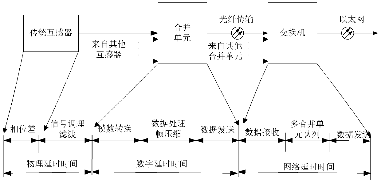
technical field [0001] The invention belongs to the technical field of digital metering of smart substations, and in particular relates to a cross-interval digital metering method, device and system based on network sampling absolute delay compensation. Background technique [0002] With the gradual popularization of smart substations and electronic transformers, digital metering systems have become an essential system for smart substations, but digital metering imbalances occur from time to time, especially in the field of cross-interval digital metering. The digital electric energy metering system is composed of electronic current / voltage transformer, merging unit, optical fiber network and digital electric energy meter. Single-bay digital energy metering technology is relatively mature. When the smart substation adopts the design of inner bridge, 3 / 2 wiring, and busbar PT cascading, the voltage and current signals of transformers located in multiple bays need to be cascad...

Claims


Application Information

Patent Timeline
IPC IPC(8): G01R22/10G01R22/06H04J3/06
Inventor 汤汉松
Owner 江苏凌创电气自动化股份有限公司
Learn More