Position trigger controlling method for CT (Computed Tomography) scanning and system for implementing method

A technology of trigger control and CT scanning, which is applied in the direction of measuring devices, material analysis using wave/particle radiation, instruments, etc., can solve the problems of fluctuations, the speed of sample stage rotation and the speed of lifting and lowering cannot be constant, etc., to achieve fast Position triggering, simplified structure and signal analysis process, accurate position information effect

Inactive Publication Date: 2019-06-28
天津三英精密仪器股份有限公司
View PDF10 Cites 2 Cited by
  • Summary
  • Abstract
  • Description
  • Claims
  • Application Information

AI Technical Summary

Problems solved by technology

In the same way, the rotation speed and lifting speed of the sample stage cannot be constant, and there are fluctuations

Method used


Image

  • Position trigger controlling method for CT (Computed Tomography) scanning and system for implementing method
  • Position trigger controlling method for CT (Computed Tomography) scanning and system for implementing method
  • Position trigger controlling method for CT (Computed Tomography) scanning and system for implementing method

Examples


Embodiment Construction

[0050] The present invention will be described in further detail below in conjunction with specific examples. The following examples are only descriptive, not restrictive, and cannot limit the protection scope of the present invention.

[0051] The raw materials used in the present invention, if no special instructions, are conventional commercially available products; the equipment used in the present invention, if no special instructions, are conventional commercially available equipment.

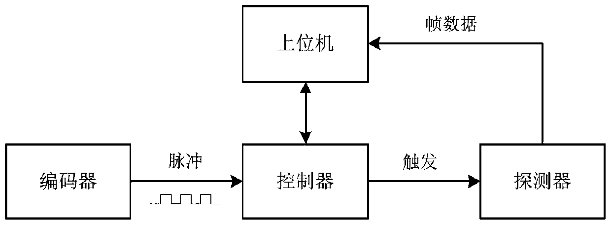
[0052] The basic principle of spiral CT scanning in the prior art is as follows: figure 1 As shown, the ray source, the sample, and the detector are in a straight line, the X-ray cone beam penetrates the sample and is projected onto the detector, the sample stage is lifted up and down, and a series of projection images (frames) are taken, and all frames are reconstructed and synthesized into a three-dimensional image, and restored The internal structure of the sample.

[0053] A position...


PUM


Abstract

The invention relates to a position trigger controlling method for CT (Computed Tomography) scanning. The method comprises the following steps: measuring the position information of a rotating shaft (and a lifting shaft) of a sample table in real time and outputting pulses by an encoder; taking pictures and collecting projected images by a detector; receiving the projected images by a host computer; and centrally coordinating by a controller. The method has the advantages that trigger signals can be directly controlled through the controller; the quick position trigger at the millisecond levelis realized; the position information is accurate; the reconstruction quality of a three-dimensional image is improved; and the structure and signal analyzing processes are simplified.

Description

technical field [0001] The invention belongs to the technical field of CT, in particular to a position trigger control method for CT scanning and a system for implementing the method. Background technique [0002] In order to meet the needs of reconstructing three-dimensional images, CT scanning requires the sample to be rotated around a certain axis within 360°, and projected images (hereinafter referred to as As a "frame"), and then use the position and projection image for processing and reconstruction through computer software to obtain a three-dimensional image. In this process, the precise matching of the two is a necessary prerequisite to ensure the quality of the reconstructed image. [0003] Existing CT scans use the following methods: [0004] 1. "Stop-and-go mode", the sample stops when it rotates to the predetermined position, and then the detector takes a frame. This method can obtain sufficiently accurate position information, but CT scanning needs to take a ...

Claims


Application Information

Patent Timeline
IPC IPC(8): G01N23/046
Inventor 张驰宇王奎华未永张园成
Owner 天津三英精密仪器股份有限公司
Why Eureka
Try Eureka