
Detection system and detection method for cracks in bridge undersurface

A crack detection and bridge technology, applied in the direction of optical testing flaws/defects, etc., can solve the problems of low detection efficiency, large detection limitations, and non-standard detection results, so as to reduce the detection cost, simplify the operation difficulty, and ensure the calculation accuracy. Effect

Active Publication Date: 2019-06-28
UNIV OF SHANGHAI FOR SCI & TECH
View PDF12 Cites 10 Cited by
  • Summary
  • Abstract
  • Description
  • Claims
  • Application Information

AI Technical Summary

Problems solved by technology

[0006] Aiming at the problems of low detection efficiency, large detection limitations, and non-standard detection results of the existing detection methods, the present invention provides a bridge bottom crack detection system and detection method, which can accurately measure the size of cement cracks on the bottom of large bridges. Industrial cameras replace manual detection of cracks on the bottom of large bridges. Operators only need to start the system through the computer, and the system will automatically scan the crack information on the bottom of the bridge to realize automatic bridge detection, greatly reduce the number of detection personnel, simplify operation difficulty, and reduce detection costs.

Method used


Image

  • Detection system and detection method for cracks in bridge undersurface
  • Detection system and detection method for cracks in bridge undersurface
  • Detection system and detection method for cracks in bridge undersurface

Examples


Embodiment Construction

[0040] In the following, the concept, specific structure and technical effects of the present invention will be further described in conjunction with the accompanying drawings to fully understand the purpose, features and effects of the present invention.

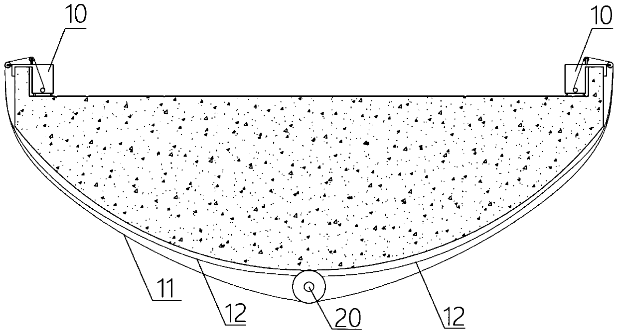
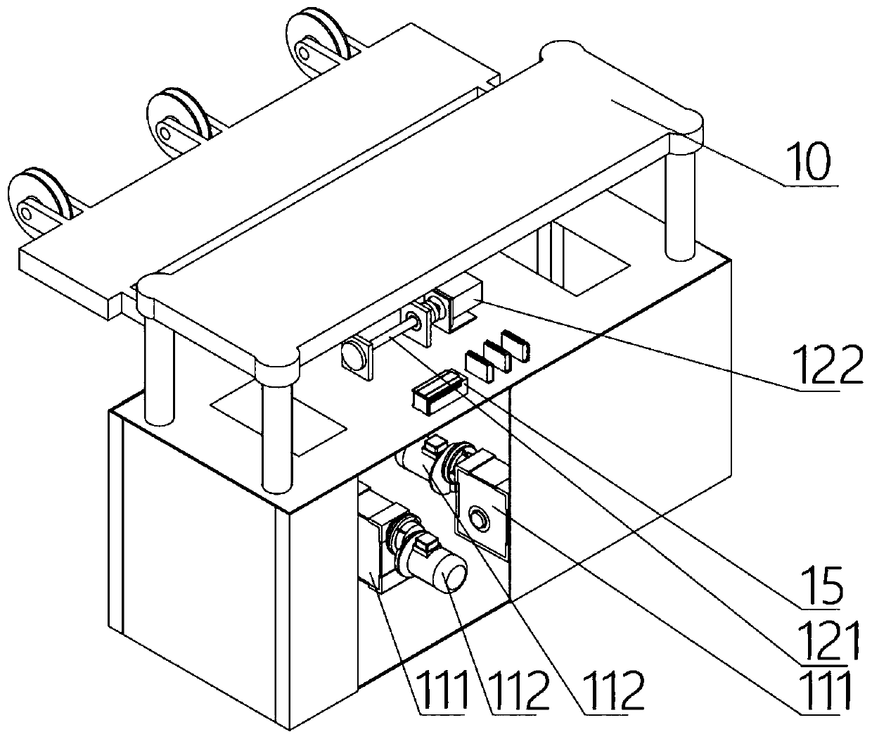
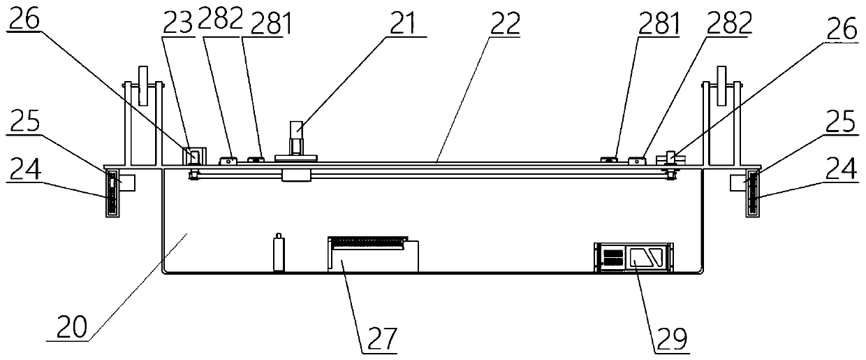
[0041] reference figure 1 The bridge bottom crack detection system of the present invention includes a cable tractor 10 running on both sides of the bridge and a crack detection vehicle 20 under the bridge. The cable tractor 10 provides support and moving power for the crack detection vehicle 20, and crack detection The car 20 performs the task of shooting and collecting crack information. A load-bearing cable 11 is connected between the cable tractors 10 on both sides of the bridge deck. The load-bearing cable 11 is hung below the bridge. The crack detection vehicle 20 uses the load-bearing cable 11 as a load-bearing and moving track and is pulled by the cable-towing vehicle 10 along the bridge. Move in the length direction. ...


PUM


Abstract

The invention relates to a detection system and a detection method for cracks in a bridge undersurface. The detection system comprises cable towing tractors traveling on the two sides of the bridge floor and a crack detection car located below a bridge, wherein each cable towing tractor is provided with a cable drum, a cable drum motor and a cable controller; the crack detection car is provided with a linear guide rail, a camera motor, pressing wheels, encoders, laser distance sensors and a detection controller, the linear guide rail is arranged on the upper surface of the crack detection car,an industrial camera is glidingly fixed on the linear guide rail, the crack detection car is glidingly fixed on a bearing cable through the pressing wheels on the two sides, the pressing wheels rotate to drive the encoder to rotate and count, and the laser distance sensor is arranged on the upper surface of the crack detection car and used for detecting distance between the crack detection car and the bridge undersurface. The detection system adapts to undersurface crack detection of a large wide-body bridge, and detection safety, detection precision and detection efficiency are improved. Automatic detection can be realized, the number of detection workers can be substantially reduced, operation difficulty is reduced, and detection cost is reduced.

Description

Technical field [0001] The invention relates to the technical field of bridge detection and maintenance, and in particular to a detection system and a detection method for cracks on the bottom surface of a bridge. Background technique [0002] During the use of the bridge, cracks will occur on the main body of the bridge cement due to vibration, natural weather, external forces and other reasons. Regular inspection of bridge cracks helps to understand the operating status of the bridge and improve the safety of the bridge. Due to the wide deck of large bridges, there may be rivers, green belts and highways under the bridge. The initial cracks on the underside of the bridge are usually small cracks that are not easy to be detected. Once a large crack is formed, the bridge has been missed. The best time to repair. The detection of the underside of large bridges has always been a difficult point in the detection of bridge cracks. [0003] At present, the detection methods for bridg...

Claims


Application Information

Patent Timeline
IPC IPC(8): G01N21/95
Inventor 王艳陈思宇杨杰王庆中吴成振
Owner UNIV OF SHANGHAI FOR SCI & TECH
Learn More