Method for measuring ultra-large curvature radius through transverse subtraction and differential confocal processing

A differential confocal and radius measurement technology, which is applied to measuring devices, instruments, and optical devices, can solve the problems of difficult precision length measurement, long measurement optical path, and low precision of fixed focus, so as to improve measurement accuracy and high precision Effect of measuring and eliminating common mode noise

Active Publication Date: 2019-06-28
BEIJING INSTITUTE OF TECHNOLOGYGY +1
View PDF17 Cites 1 Cited by
  • Summary
  • Abstract
  • Description
  • Claims
  • Application Information

AI Technical Summary

Problems solved by technology

[0012] 1) The focal depth is long, affected by the diffraction effect, the focus accuracy of "cat's eye" and "confocal position" is low;
[0013] 2) The radius is large and the measurement optical path is long, which is difficult to measure precisely due to the interference of the measurement environment and system drift;

Method used


Image

  • Method for measuring ultra-large curvature radius through transverse subtraction and differential confocal processing
  • Method for measuring ultra-large curvature radius through transverse subtraction and differential confocal processing
  • Method for measuring ultra-large curvature radius through transverse subtraction and differential confocal processing

Examples


Embodiment 1

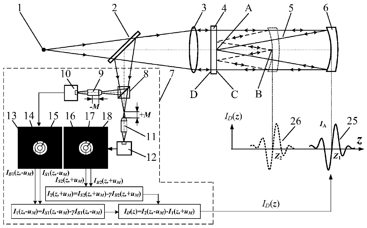
[0044] as attached Figure 6 As shown, the measurement steps of the lateral subtraction differential confocal ultra-large radius of curvature measurement method disclosed in this embodiment are:

[0045] When the spherical element 6 to be tested is a concave lens with a diameter of D=150mm, the measurement of the super large radius of curvature of the bilateral misalignment differential confocal is shown in the attached Figure 5 As shown, the measurement steps of the bilateral dislocation differential confocal ultra-large radius of curvature measurement method are:

[0046] a) Start the measurement software of the main control computer 30, turn on the laser 34, and the light emitted by the laser 34 passes through the microscope objective lens 35 and the pinhole 36 to form a point light source 1. The light emitted by the point light source 1 passes through the beam splitter 2 , the collimating lens 3 and the parallel flat crystal 4 and then irradiates on the spherical element...

Embodiment 2

[0057] When the spherical element 6 to be tested is a concave lens with a diameter of D=150mm, the measurement of the super large radius of curvature of the bilateral misalignment differential confocal is shown in the attached Figure 6 As shown, the measurement steps of the bilateral dislocation differential confocal ultra-large radius of curvature measurement method are:

[0058] a) Start the measurement software of the main control computer 30, turn on the laser 34, and the light emitted by the laser 34 passes through the microscope objective lens 35 and the pinhole 36 to form a point light source 1. The light emitted by the point light source 1 passes through the beam splitter 2 , the collimating lens 3 and the parallel flat crystal 4 and then irradiates on the spherical element 6 to be tested.

[0059] b) Adjust the measured spherical element 6 so that it has the same optical axis as the parallel flat crystal 4 and the collimator lens 3, so that the parallel light beam em...


PUM


Abstract

The invention discloses a method for measuring an ultra-large curvature radius through transverse subtraction and differential confocal processing and belongs to the technical field of optical precision detection. According to the method, in a confocal measurement system, firstly, a large and small virtual pinhole detection area (image area) is set through software on a CCD detected airy disk image through software, two confocal characteristic curves detected by a CCD are subjected to subtraction processing to sharpen the confocal characteristic curves, finally, all characteristic points in ultra-large curvature radius measurement are subjected to high-precision fixed focusing by use of the characteristic that a zero point of a transverse subtraction and differential confocal characteristic curve and a focus of the measurement system correspond to each other precisely, and further, high-precision measurement of the ultra-large curvature radius is realized. The method provides a brand-new technical way for high-precision measurement of the ultra-large curvature radius.

Description

technical field [0001] The invention relates to a method for measuring a super large curvature radius by lateral subtraction and differential confocal, and belongs to the technical field of precision measurement of optical element parameters. Background technique [0002] In optical systems, inertial navigation systems, and aircraft engine transmission systems, spherical elements are one of the most important elements. The radius of curvature of the spherical element is the most critical parameter to determine the overall performance of the element, so it is of great significance to measure the radius of curvature of the spherical element with high precision. [0003] For the measurement of the radius of curvature of a spherical surface, the existing measurement methods are: spherical template method, spherometer method, self-collimation method, interferometer method, knife-edge meter method, Newton ring method, laser shearing interferometer method and Mohr Segregation meth...

Claims


Application Information

Patent Timeline
Patent Type & Authority Applications(China)
IPC IPC(8): G01B11/255
Inventor 赵维谦刘文丽肖阳邱丽荣
Owner BEIJING INSTITUTE OF TECHNOLOGYGY
Why Eureka
Try Eureka