
Multi-joint spine and spine four-foot robot

A quadruped robot, multi-joint technology, applied in the field of robotics, can solve the problems of inability to bend the torso, limited movement speed and flexibility, and inconsistency with biological movement patterns, so as to increase operability and enrich the diversity of bending shapes. , the effect of increasing running speed

Active Publication Date: 2019-06-28
HARBIN INST OF TECH
View PDF6 Cites 2 Cited by
  • Summary
  • Abstract
  • Description
  • Claims
  • Application Information

AI Technical Summary

Problems solved by technology

Existing quadruped robots generally use a rigid body, the trunk cannot be bent, the speed and flexibility of movement are severely limited, and it does not conform to the shape of biological movement. The existing technology is still difficult to solve

Method used


Image

  • Multi-joint spine and spine four-foot robot
  • Multi-joint spine and spine four-foot robot
  • Multi-joint spine and spine four-foot robot

Examples


Embodiment 1

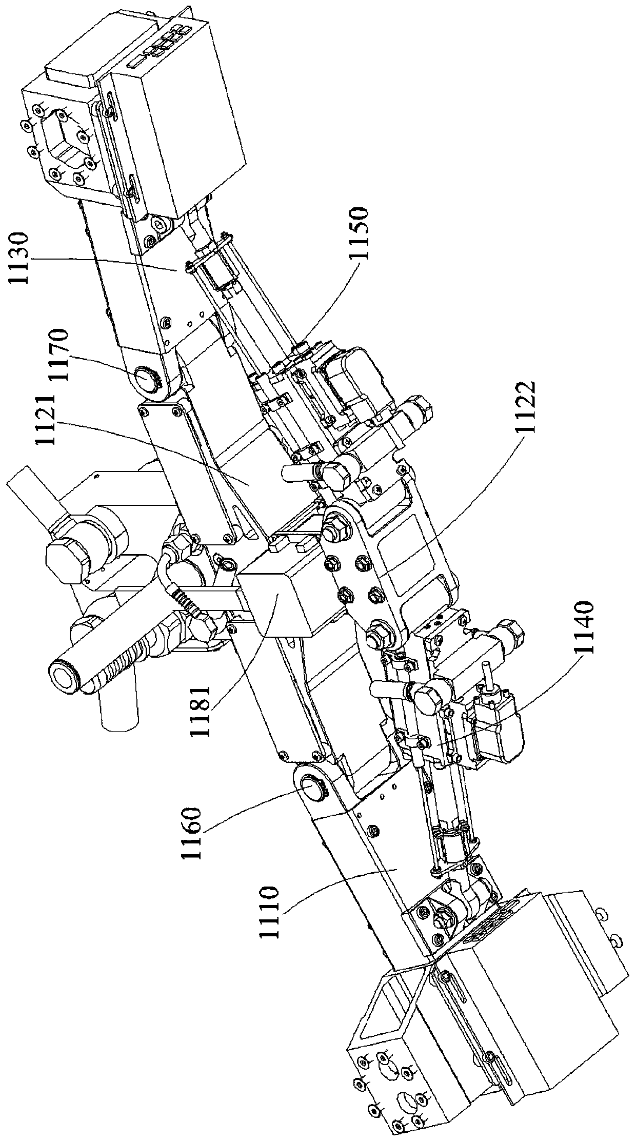
[0032] Please refer to Figure 1~3 This embodiment discloses a multi-joint spine 1100. The multi-joint spine 1100 includes a first spine 1110, a second spine 1120, and a third spine 1130 that are hinged in sequence to form a three-segment main body joint structure, thereby simulating four The spine bending movement of the foot creature improves the movement speed and movement flexibility of the quadruped robot.

[0033] Based on the articulation relationship, the first spine 1110 and the third spine 1130 can respectively rotate around the articulation axis of the second spine 1120 and itself to realize the bending motion of the multi-joint spine 1100. Under the aforementioned structure, the multi-joint spine 1100 has a three-stage basic configuration. The three-stage basic configuration has a wide bending angle, which can achieve large body bending, thereby effectively increasing the running distance. At the same time, the three-stage basic configuration of the spine motion law ...

Embodiment 2

[0046] See Figure 4 This embodiment discloses a spine-type quadruped robot 1000. The spine-type quadruped robot 1000 includes the multi-joint spine 1100 and the lower limb 1200 described in the first embodiment. As mentioned above, the lower limbs of the robot 1200 are respectively installed on the first spine 1110 and the third spine 1130, so that the robot has four limbs (which can be divided into fore and hind limbs).

[0047] Among them, the front and rear limbs of the robot can be formed by a linear array of the lower limbs 1200 of the robot, with the same orientation, forming, for example, " > "Shaped legs distribution and other structural forms. Or, the front and rear limbs of the robot have a symmetrical distribution relationship. Exemplarily, in the latter form, the lower limb 1200 of the robot located on the first spine 1110 and the lower limb 1200 of the robot located on the third spine 1130 It is symmetrical about the second spine 1120. In the symmetrical form, the f...


PUM


Abstract

The invention discloses a multi-joint spine. The multi-joint spine comprises a first chine, a second chine and a third chine hinged in sequence; the first chine and the third chine are used for mounting robot lower limbs; the first chine is connected with a first driving unit for driving the first chine to rotate around the hinged shaft; the third chine is connected with a second driving unit fordriving the third chine to rotate around the hinged shaft; and the first driving unit and the second driving unit are mounted on the second chine. The invention further discloses a spine four-foot robot; the spine four-foot robot comprises the multi-joint spine and the robot lower limbs; and the robot lower limbs are mounted on the first chine and the third chine. The multi-joint spine and the spine four-foot robot; and the robot has the multi-joint spine structure to simulate spine bending actions of four-foot organisms, so that the spine bending amplitude is wide, the motion independence andoperability of front and back limbs are improved, and the motion speed and the motion flexibility of the four-foot robot are improved.

Description

Technical field [0001] The invention belongs to the technical field of robots, and specifically, is a multi-joint spine and spine quadruped robot. Background technique [0002] Footed robots are one of the most cutting-edge topics in the field of robotics research today. It integrates multiple disciplines such as mechanics, electronics, computers, materials, sensors, control technology, and artificial intelligence. The interdisciplinary and high degree of complexity has attracted many scientific researches. With the focus of institutions and technology companies, countries have also invested heavily in research. The existing quadruped robot generally adopts a rigid body, the torso cannot be bent, the movement speed and movement flexibility are severely restricted, and it does not conform to the biological movement form, and the existing technology is still difficult to solve. Summary of the invention [0003] In order to overcome the shortcomings of the prior art, the present inv...

Claims


Application Information

Patent Timeline
IPC IPC(8): B25J9/00B25J17/00
Inventor 郭伟蔡昌荣李贺琦
Owner HARBIN INST OF TECH
Learn More