Laser marking machine for steel bar marking

A technology of laser marking machine and steel bar, applied in the field of laser marking machine, can solve the problems of slow marking speed, low efficiency, unclear marking, etc., and achieve the effect of clear marking and improved work efficiency.

Pending Publication Date: 2019-06-28
南京德阳科技有限公司
View PDF0 Cites 2 Cited by
  • Summary
  • Abstract
  • Description
  • Claims
  • Application Information

AI Technical Summary

Problems solved by technology

[0002] In order to measure the elongation of the steel bar, it is necessary to mark the original gauge length on the sample steel bar before the experiment. The existing steel bar gauge length is realized by a dotting machine. The principle is generally to use a steel needle to dot the sample. The speed is slow, the marking is not clear, and each gauge length can only act on one steel bar, so the efficiency is low

Method used


Image

  • Laser marking machine for steel bar marking
  • Laser marking machine for steel bar marking

Examples


Embodiment Construction

[0012] The present invention will be further described below in conjunction with the accompanying drawings.

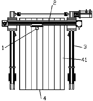
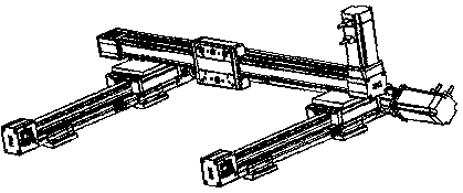
[0013] Such as figure 1 and figure 2 , the present invention is a kind of laser marking machine that is used for steel bar gauge, comprises laser head 1, X-axis moving mechanism 2, Y-axis moving mechanism 3 and steel bar placing table 4, two Y-axis moving mechanisms 3 are arranged parallel to each other, X-axis The two ends of the moving mechanism 2 are fixedly connected to the free ends of the two Y-axis moving mechanisms 3, the laser head 1 is fixed on the free ends of the X-axis moving mechanisms 2, and the steel bar placement platform 4 is placed between the two Y-axis moving mechanisms 3, The laser head 1 is located above the steel bar placement platform 4, and several limiting grooves 41 are arranged on the steel bar placing platform 4, and the limiting grooves 41 are arranged along the moving direction of the free end in the Y-axis moving mechanism 3 .

[001...


PUM


Abstract

The invention discloses a laser marking machine for steel bar marking. The laser marking machine comprises a laser head, an X-axis moving mechanism, Y-axis moving mechanisms and a steel bar placing table, two Y-axis moving mechanisms are arranged in parallel, the two ends of the X-axis moving mechanism are fixedly connected to the free ends of the two Y-axis moving mechanisms, the laser head is fixed to the free end of the X-axis moving mechanism, the steel bar placing table is arranged between the two Y-axis moving mechanisms, the laser head is located above the steel bar placing table, a plurality of limiting grooves are formed in the steel bar placing table, and the limiting grooves are arranged in the moving direction of the free end in the Y-axis moving mechanisms. A plurality of reinforcing steel bars are marked by laser through a moving mechanism in the XY direction, the marking distance and the marking position are controlled by the stepping motor, the marking line is clear, batch marking can be carried out, and the working efficiency is greatly improved.

Description

Technical field: [0001] The invention relates to a laser marking machine for steel bar gauge. Background technique: [0002] In order to measure the elongation of the steel bar, it is necessary to mark the original gauge length on the sample steel bar before the experiment. The existing steel bar gauge length is realized by a dotting machine. The principle is generally to use a steel needle to dot the sample. The speed is slow, the marking is not clear, and each gauge length can only act on one steel bar, so the efficiency is low. Invention content: [0003] The present invention provides a laser marking machine for the steel bar gauge in order to solve the above-mentioned problems in the prior art. [0004] The technical solutions adopted in the present invention include: a laser marking machine for steel bar gauge, including a laser head, an X-axis moving mechanism, a Y-axis moving mechanism and a steel bar placement table, and the two Y-axis moving mechanisms are arran...

Claims


Application Information

Patent Timeline
Patent Type & Authority Applications(China)
IPC IPC(8): B23K26/362B23K26/08
Inventor 陈松
Owner 南京德阳科技有限公司
Why Eureka
Try Eureka