Three-point locating type craniocerebral operation locating device
A craniocerebral surgery and positioning device technology, applied in stereotaxic surgical instruments, surgery, operating tables, etc., can solve the problems that cranial surgery head frame cannot be directly installed on the bed body, affects the fixation effect, and has insufficient stability. Achieve the effect of improving the head fixation effect, facilitating multi-angle installation, and improving the clamping stability
- Summary
- Abstract
- Description
- Claims
- Application Information
AI Technical Summary
Problems solved by technology
Method used
Image
Examples
Embodiment 1
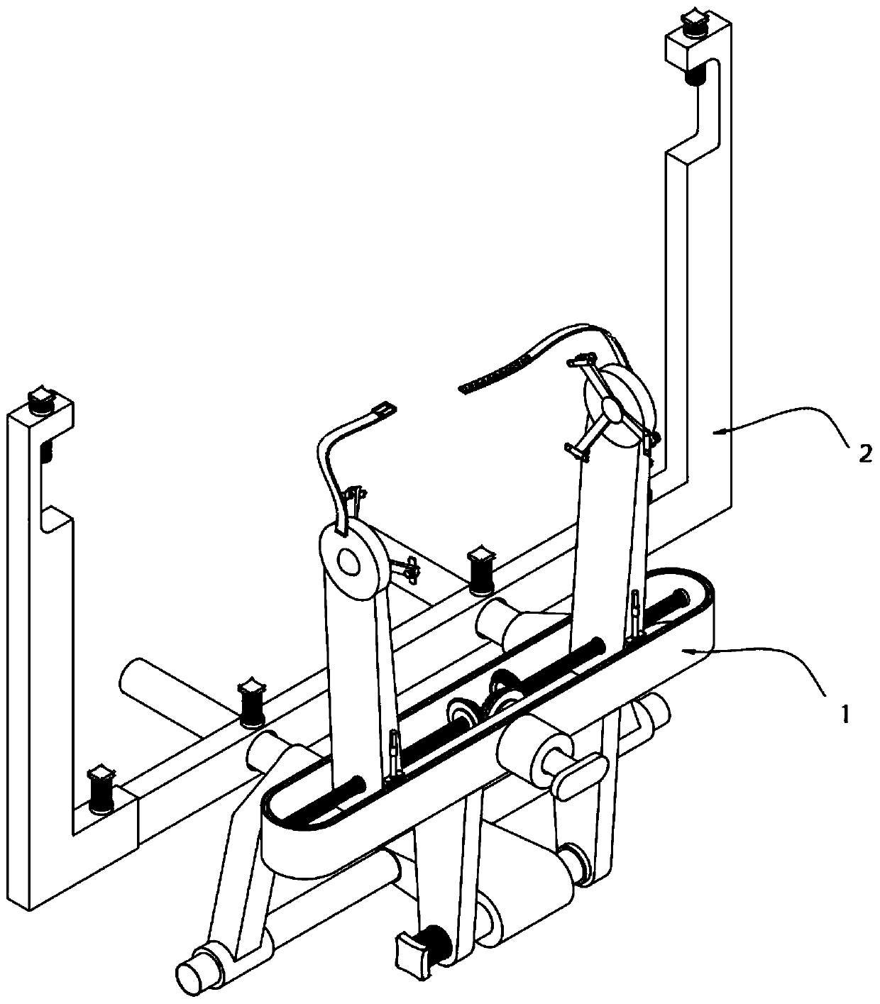
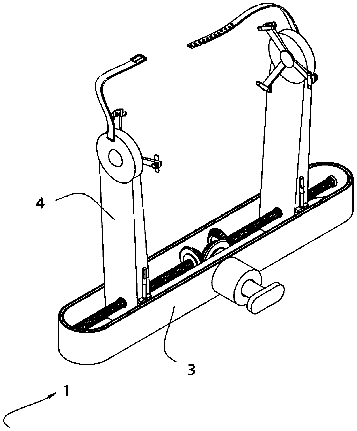
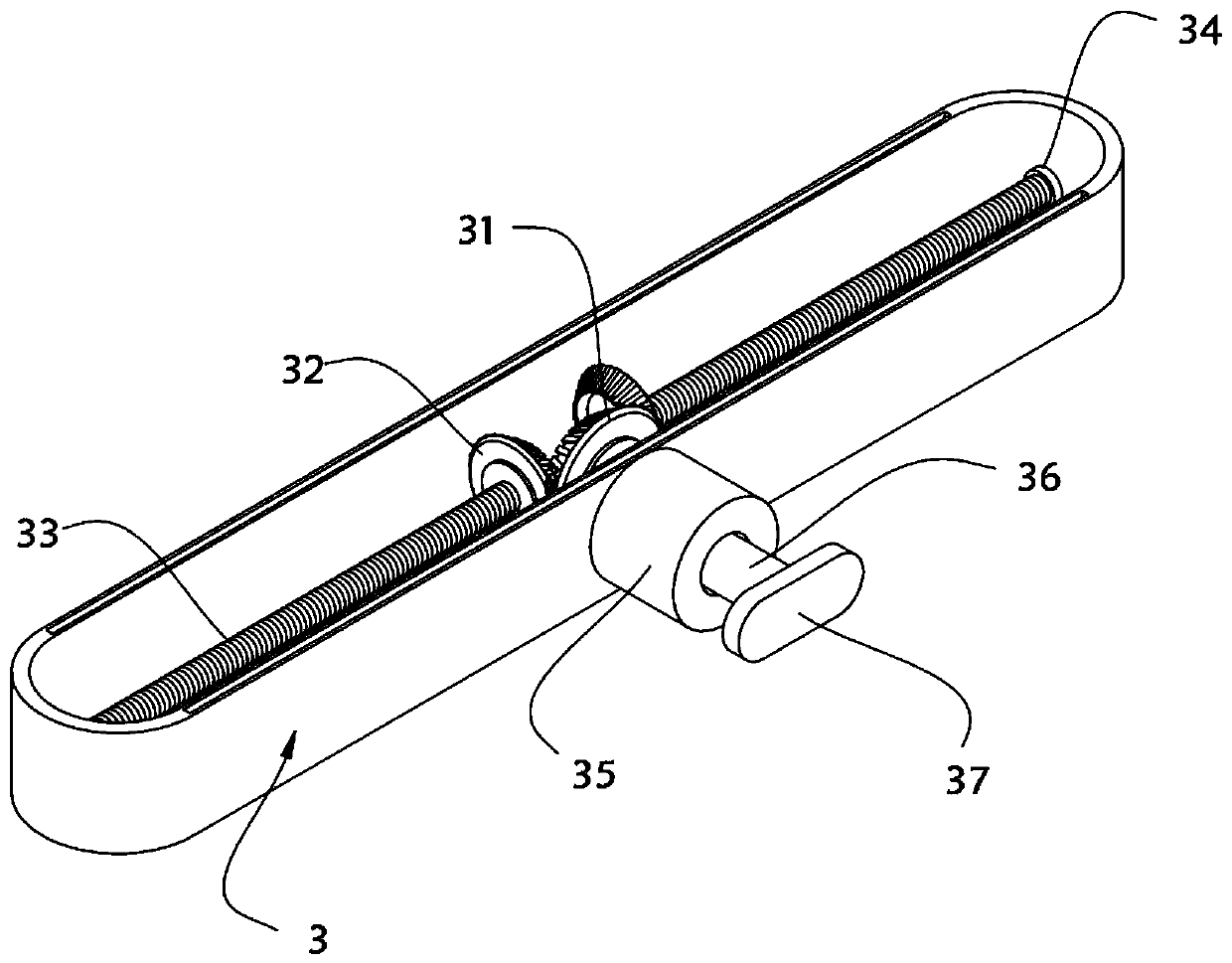
[0037] The present invention provides a three-point positioning craniocerebral surgery positioning device, such as Figure 1-Figure 4As shown, it includes a cranial fixation device 1 for fixing the skull and a fixed installation assembly 2 for installing the cranial fixation device 1. The cranial fixation device 1 includes an adjustment box 3 and a skull clamp 4 installed inside the adjustment box 3 , the center position of the adjustment box 3 is equipped with an active bevel gear 31, and the two sides of the active bevel gear 31 are symmetrically equipped with a drive bevel gear 32, and the drive bevel gear 31 and the drive bevel gear 32 mesh, and one end of the drive bevel gear 32 is welded with a ball Lead screw 33, the other end of ball screw 33 is rotatably connected with the inner wall of adjustment box 3 through first bearing ring 34, and head fixture 4 comprises a pair of splints 41, and the outer surface of splint 41 is installed with ball screw 33 threads. The ball ...
Embodiment 2
[0043] As the second embodiment of the present invention, in order to facilitate the head positioning plate 43 to fit the patient's skull more closely for clamping, the inventors made improvements to the head positioning plate 43, as a preferred embodiment, as Figure 5 and Figure 6 As shown, the inner wall of the head positioning plate 43 is equipped with a mounting plate 431, and the outer wall of the mounting plate 431 has a plurality of clamping strips 432 in an annular array. 434, the fitting part 434 includes a sliding column 435, the sliding column 435 and the through hole 433 are slidingly fitted, one end of the sliding column 435 is equipped with a fitting plate 436, and the other end of the sliding column 435 is equipped with a limiting plate 437, the size of the limiting plate 437 Larger than the size of the through hole 433 , the outer wall of the bonding plate 436 is provided with a plurality of bonding blocks 438 .
[0044] In this embodiment, the clamping stri...
Embodiment 3
[0049] As a third embodiment of the present invention, in order to facilitate the fixing of the splint 41, the inventors also set a limiting plate 47, as a preferred embodiment, such as Figure 7 and Figure 8 As shown, the outer walls on both sides of the splint 41 are respectively provided with limiters 47, the top of the adjustment box 3 is provided with a pair of slots 38, the limiter 47 includes a fixed cylinder 471 installed on the outer wall of the splint 41, and the fixed cylinder 471 is provided with Push rod 472, the top side of the outer wall of the push rod 472 is equipped with an outwardly protruding bump 473, and the top of the fixed cylinder 471 is provided with an inwardly concave groove 476, and the size of the bump 473 is compatible with the size of the groove 476 Matching, the bottom of the push rod 472 is equipped with an insert block 474 that is plugged and matched with the slot 38, and the push rod 472 and the insert block 474 are rotationally connected t...
PUM
 Abstract
Description
Claims
Application Information
 - R&D
- Intellectual Property
- Life Sciences
- Materials
- Tech Scout
- Unparalleled Data Quality
- Higher Quality Content
- 60% Fewer Hallucinations
Browse by: Latest US Patents, China's latest patents, Technical Efficacy Thesaurus, Application Domain, Technology Topic, Popular Technical Reports.
© 2025 PatSnap. All rights reserved.Legal|Privacy policy|Modern Slavery Act Transparency Statement|Sitemap|About US| Contact US: help@patsnap.com


