
Magnetron antenna assembly

A technology for antenna components and magnetrons, applied in magnetrons, antenna supports/mounting devices, electrical components, etc., can solve problems such as increased costs, low output efficiency, unfavorable test processing, etc., to reduce discharge and improve The effect of service life and reducing the probability of sparking and generating electricity

Pending Publication Date: 2019-06-25
ANDESON SUPERCONDUCTING RF ACCELERATOR TECHCO
View PDF0 Cites 0 Cited by
  • Summary
  • Abstract
  • Description
  • Claims
  • Application Information

AI Technical Summary

Problems solved by technology

[0002] At present, the design output efficiency of the magnetron antenna and output window on the market is not high, and it is necessary to install a matching excitation cavity to improve the coupling transmission efficiency of microwaves, which increases the cost. At the same time, it is not conducive to testing and processing due to the need for excitation cavity

Method used


Image

  • Magnetron antenna assembly
  • Magnetron antenna assembly
  • Magnetron antenna assembly

Examples


Embodiment Construction

[0027] The following will clearly and completely describe the technical solutions in the embodiments of the present invention with reference to the drawings in the embodiments of the present invention.

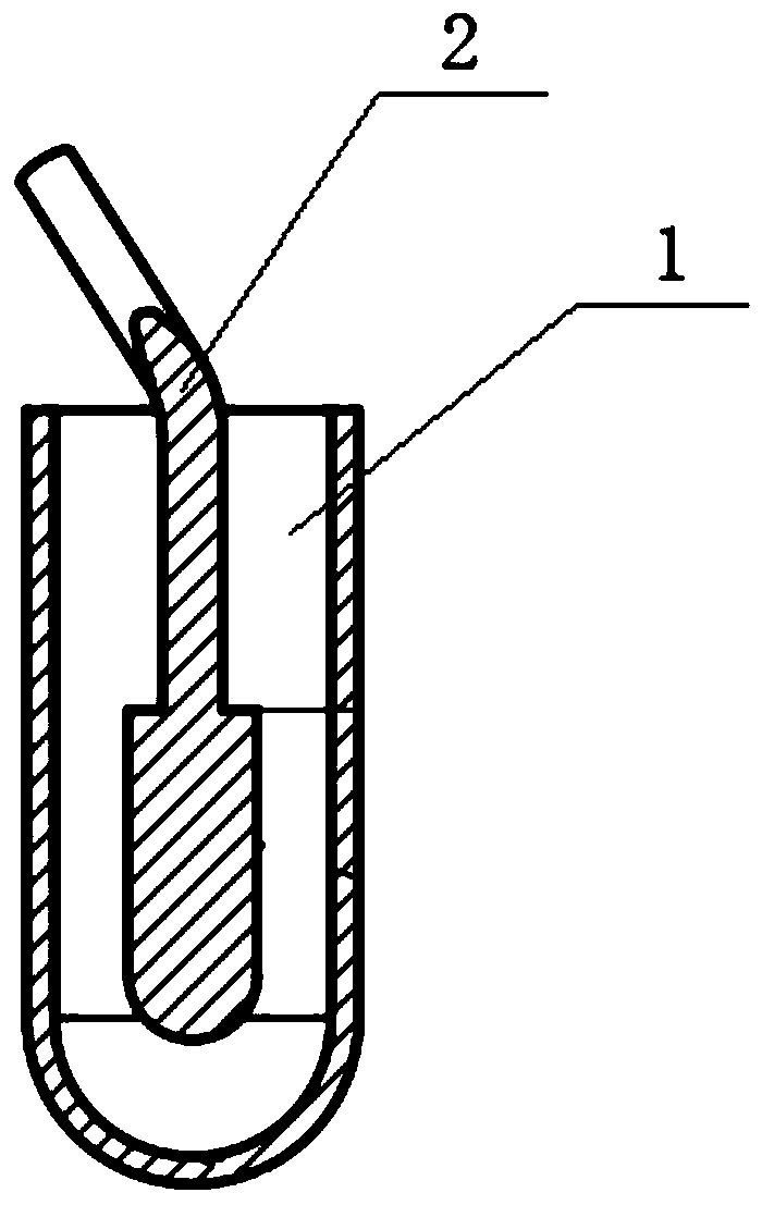
[0028] The invention provides a magnetron antenna assembly, the working principle of which is to optimize the design of the antenna and the output window, so that the magnetron antenna assembly has good transmission efficiency, and also reduces the requirements of the magnetron antenna assembly on the excitation cavity , to achieve the purpose of improving the transmission efficiency of microwave coupling, reducing the cost and reducing the matching degree between the antenna and the excitation cavity.

[0029] The present invention will be described in further detail below in conjunction with examples and specific implementation methods.

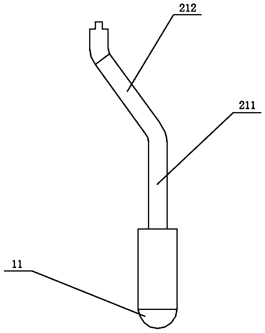
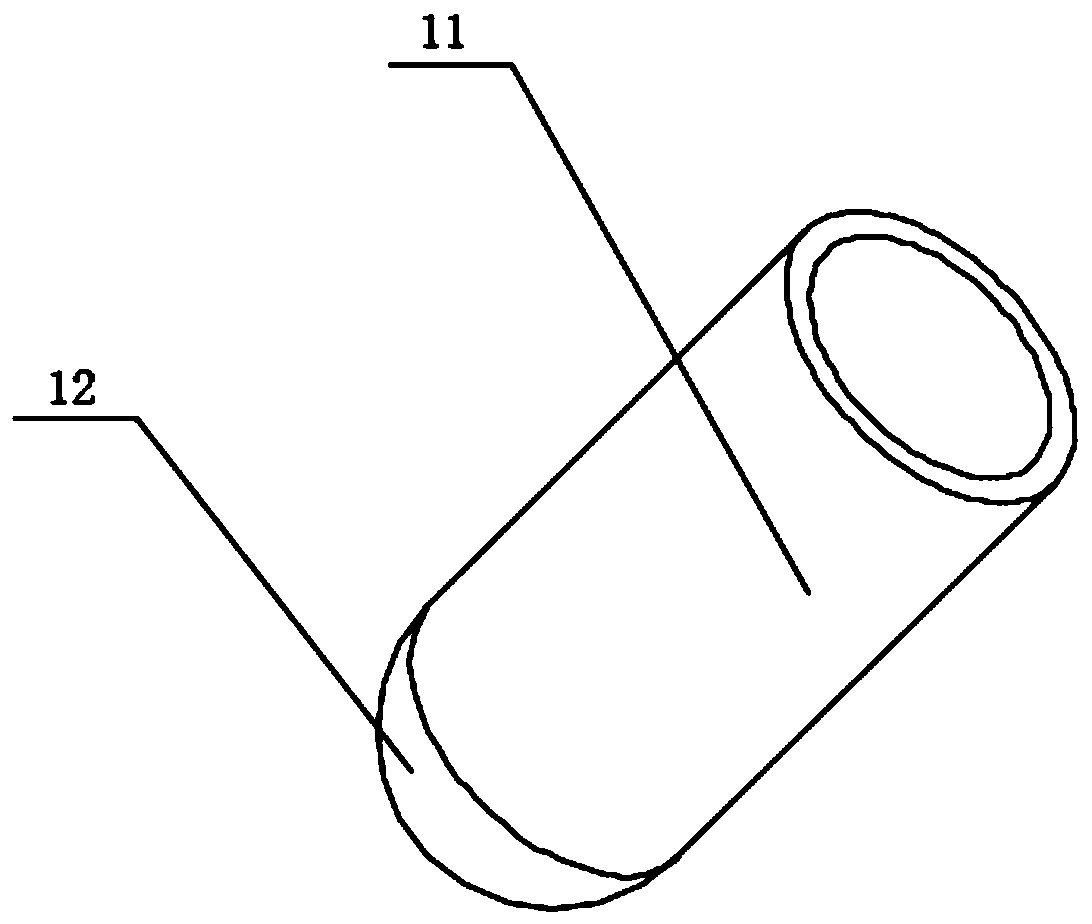
[0030] like Figure 1-Figure 3 As shown, a magnetron antenna assembly includes an output window 1 made of ceramics set on the excitation ...


PUM


Abstract

The invention discloses a magnetron antenna assembly comprising an output window made of ceramic on an excitation cavity and an antenna disposed on the output window, wherein the output window is provided therein with a mounting slot matching the antenna; the antenna includes an antenna body and a hemispherical pendant disposed at the bottom of the antenna body. By the optimization design of the antenna and output window, the magnetron antenna assembly has good transmission efficiency, and is reduced in requirements for the excitation cavity, thereby improving the transmission efficiency of microwave coupling, reducing cost and reducing the matching degree of the antenna and the excitation cavity.

Description

technical field [0001] The invention relates to the technical field of magnetron application, in particular to a magnetron antenna assembly with high transmission efficiency. Background technique [0002] The design output efficiency of the magnetron antenna and output window on the market is not high at present. It is necessary to install a matching excitation cavity to improve the coupling transmission efficiency of microwaves, which increases the cost. At the same time, it is not conducive to testing and processing due to the need for excitation cavity. [0003] The information disclosed in this Background section is only intended to enhance the understanding of the general background of the present invention, and should not be considered as an acknowledgment or any form of suggestion that the information constitutes the prior art that is already known to those skilled in the art. Contents of the invention [0004] In order to solve the above technical problems, the pre...

Claims


Application Information

Patent Timeline
IPC IPC(8): H01Q1/36H01Q1/22H01P1/08H01J25/50
Inventor 李文亮刘友春孙安李俊周许世全侯瑞周博文张力平
Owner ANDESON SUPERCONDUCTING RF ACCELERATOR TECHCO
Learn More