
Disk lock scaffold

A scaffolding and buckle technology, which is applied to the accessories of scaffolding, the connection of scaffolding, the support of building structures, etc., can solve the problems of complicated manufacturing process, inconvenient use and disassembly, and low safety performance, and achieve good fixing firmness and fastening High firmness and easy to use

Inactive Publication Date: 2019-06-25
CHINA CONSTR SEVENTH ENG BUREAU THE SECOND CO LTD
View PDF15 Cites 3 Cited by
  • Summary
  • Abstract
  • Description
  • Claims
  • Application Information

AI Technical Summary

Problems solved by technology

At present, the connection nodes of the buckle-type scaffolding on the market, the vertical pole and the connecting flange are generally set in an integrated way. Although it is more convenient to use, the manufacturing process is more complicated and cumbersome, and the strength is not particularly high, and it is easy to be damaged; in addition, the horizontal The fixing of the rod, the inclined rod and the connected flange is fixed by a bolt, and the common bolt is generally made of a metal rod with a large end and a small end. During use, a hammer is used to hit the upper end of the bolt and fix it into the hole of the bolt. Although the strength of this kind of latch is high, it is inconvenient to use and disassemble, the firm performance of fixing cannot be guaranteed, and the safety performance is not high.
At the same time, in the current use of the buckle-type scaffolding, there is no special diagonal brace. Generally, ordinary diagonal rods are used to replace them. However, when ordinary diagonal rods are fixed, because there is no special fixed base, they can only be directly fixed on the ground. , but there will be disadvantages that cannot be adjusted, inconvenient to use, and fixed

Method used


Image

  • Disk lock scaffold
  • Disk lock scaffold
  • Disk lock scaffold

Examples


Embodiment Construction

[0021] combined with Figure 1-4 , the specific embodiment of the present invention is described as follows:

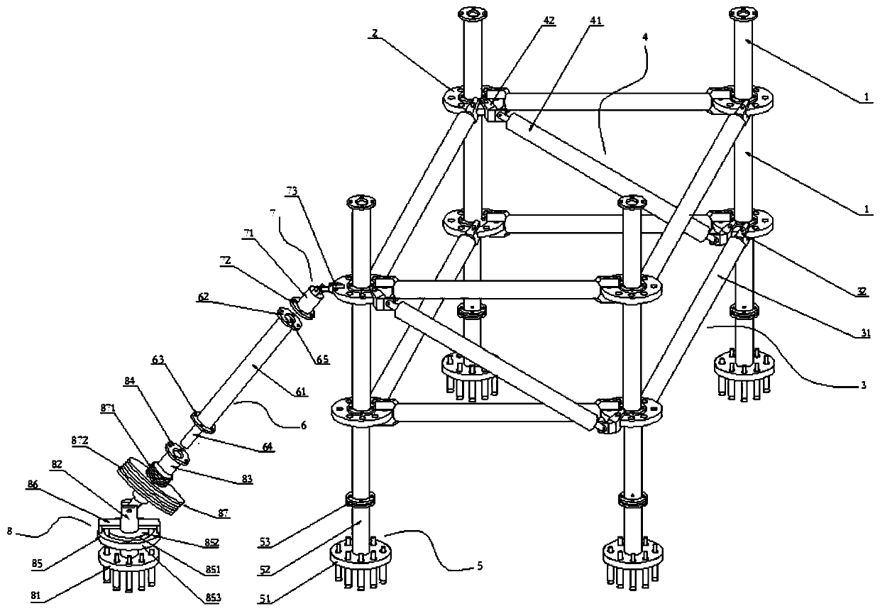
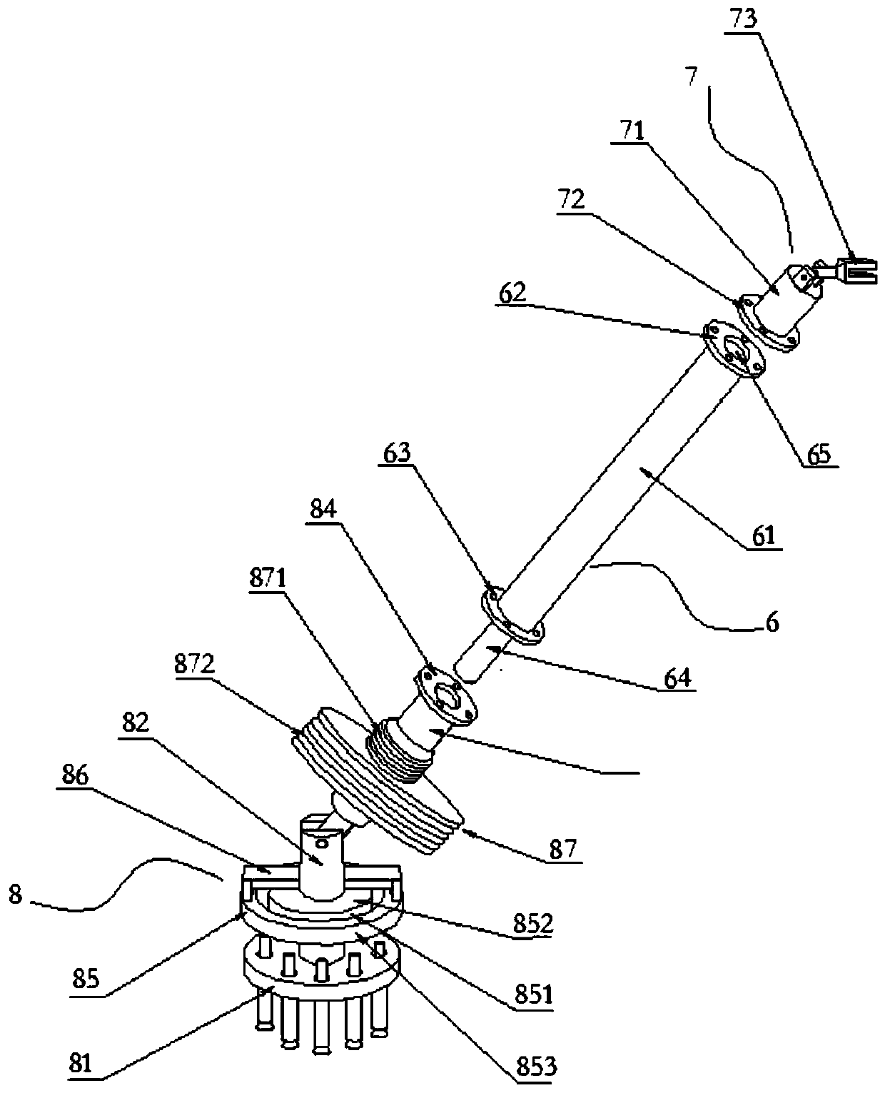
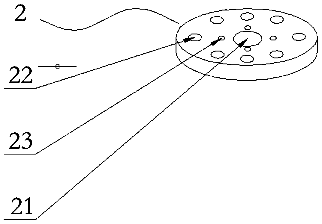
[0022] Such as Figure 1-4 As shown, a buckle-type scaffolding includes a vertical rod assembly constituting the scaffold body, a horizontal rod assembly 3, a diagonal rod assembly 4, and a diagonal brace assembly. The vertical rod assembly includes a vertical rod 1, a connecting flange 2, And the fixed base assembly 5, the vertical rod 1 is provided with several and connected in series in the vertical direction, the connecting flange 2 is provided with several and respectively arranged between two adjacent vertical rods 1 connected in series, the fixed base assembly 5 It is arranged at the bottom end of several vertical poles 1 connected in series; there are four or more vertical pole assemblies, and they are all arranged vertically; The two ends of the rod assembly 3 are respectively fixed on two connecting flanges 2 of the same height of two adjacent vertical rod...


PUM


Abstract

The invention relates to a disk lock scaffold in particular, comprising a vertical pole assembly, a horizontal pole assembly, a diagonal pole assembly and a diagonal brace assembly constituting a scaffold body, wherein the vertical pole assembly comprises a vertical pole, a connecting flange plate and a fixed base assembly, and the fixed base assembly is provided in the very bottom of a pluralityof vertical poles in series; there are four or more vertical pole assemblies, which are all provided vertically; there are a plurality of horizontal pole assemblies, diagonal pole assemblies and diagonal brace assemblies, and two ends of the horizontal pole assembly are respectively fixed on the two connecting flange plates of the same height of two adjacent vertical pole assemblies; two ends of the diagonal rod assembly are respectively fixed on the two connecting flange plates of different heights of two adjacent vertical pole assemblies; the diagonal brace assembly is provided on the outerside of the scaffold body, and the upper end of the diagonal brace assembly is fixed on the connecting flange plate of the vertical rod assembly in the outer side end of the scaffold body. The disk lock scaffold provided in the invention is convenient to use, firm and durable, very strong, convenient to disassemble, very steady for fixation and safe and reliable.

Description

technical field [0001] The invention belongs to the technical field of building construction devices, and in particular relates to a buckle-type scaffolding. Background technique [0002] In the process of building construction, scaffolding is a commonly used construction tool, which is a working platform set up to ensure the smooth progress of each construction process. According to the position of erection, it can be divided into external scaffolding and internal scaffolding; according to different materials, it can be divided into wooden scaffolding, bamboo scaffolding, steel pipe scaffolding, etc.; according to the structure form, it can be divided into vertical pole scaffolding, bridge scaffolding, portal scaffolding and suspension scaffolding , Hanging scaffolding, pick-up scaffolding, climbing scaffolding, buckle-type scaffolding, etc. [0003] The connection node technology of the buckle scaffold originated in Germany and is a mainstream product in Europe and Americ...

Claims


Application Information

Patent Timeline
IPC IPC(8): E04G1/06E04G5/02E04G5/16E04G7/22
Inventor 管珞王海鱼何兆利周文斌
Owner CHINA CONSTR SEVENTH ENG BUREAU THE SECOND CO LTD
Learn More