Punching machine trolley lifting and clamping mechanism

A clamping mechanism and trolley technology, which is applied to presses, manufacturing tools, etc., can solve the problems of difficult synchronization of multiple mechanisms, occupying the size of the punch press, and complex structure, achieving stable lifting and clamping, small size, The effect of high structural strength

Inactive Publication Date: 2019-06-25
NINGBO BOXIN MACHINERY
View PDF1 Cites 2 Cited by
  • Summary
  • Abstract
  • Description
  • Claims
  • Application Information

AI Technical Summary

Problems solved by technology

[0004] Although the mechanism in the above-mentioned patent has an integrated structure of lifting and clamping, its structure is complicated, and ...

Method used


Image

  • Punching machine trolley lifting and clamping mechanism
  • Punching machine trolley lifting and clamping mechanism
  • Punching machine trolley lifting and clamping mechanism

Examples


Embodiment Construction

[0014] Below in conjunction with specific embodiment, further illustrate the present invention. It should be understood that these examples are only used to illustrate the present invention and are not intended to limit the scope of the present invention. In addition, it should be understood that after reading the teachings of the present invention, those skilled in the art can make various changes or modifications to the present invention, and these equivalent forms also fall within the scope defined by the appended claims of the present application.

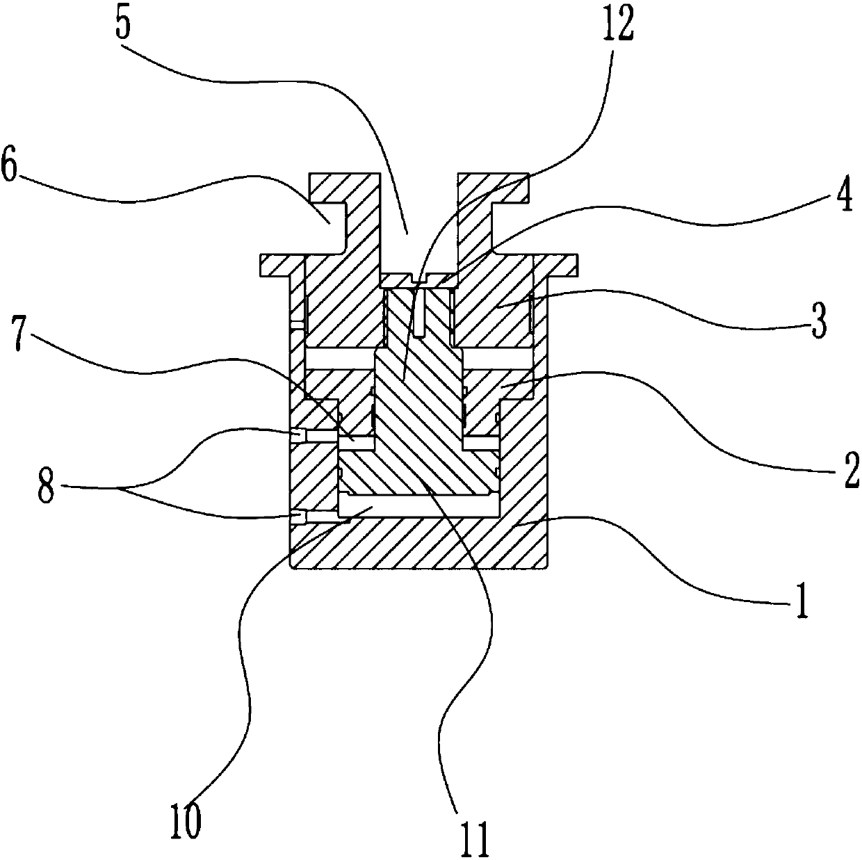
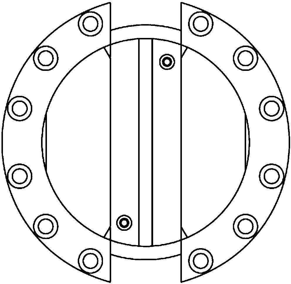
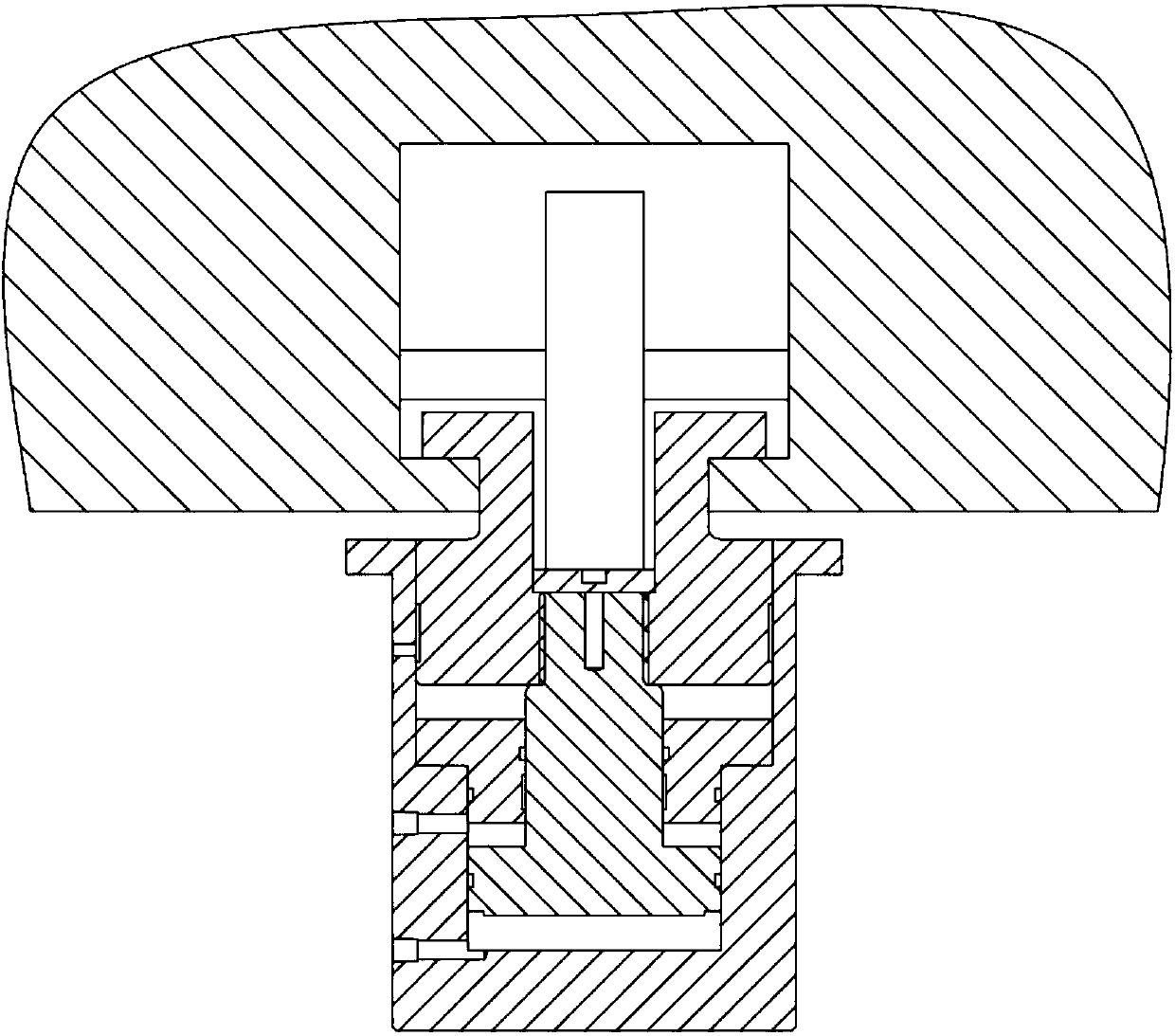
[0015] Such as Figure 1-3 As shown, the embodiment of the present invention relates to a lifting and clamping mechanism for a punch trolley, including a cylinder body 1 and a clamper 3. The upper end of the cylinder body 1 is open and a gland 2 is fixedly installed in the middle of the inner side. A piston 11 is mounted up and down on the lower side of the gland 2, and a clamper 3 is arranged to slide up and down at the upper...


PUM


Abstract

The invention relates to a punching machine trolley lifting and clamping mechanism which comprises an oil cylinder main body and a gripper; the upper end of the oil cylinder main body is opened; the middle part of the inner side of the oil cylinder main body is provided with a gland; the lower side of the gland is provided with a piston in an up-down lifting manner; the opening in the upper end ofthe oil cylinder body is provided with the gripper in an up-down sliding manner; a through groove is formed in the middle part of the gripper in a radial direction; an axial piston rod of the pistonpenetrates through the gland upwards to extend into the lower end of the through groove of the gripper; and the upper end of the axial piston rod is provided with a rail which is arranged in the through groove. The punching machine trolley lifting and clamping mechanism is simple in structure, small in size, convenient to install, high in structural strength and relatively stable in lifting and clamping.

Description

technical field [0001] The invention relates to the field of punch structure, in particular to a lifting and clamping mechanism of a punch trolley. Background technique [0002] At present, with the continuous increase in labor costs and resource costs, and the country's emphasis on safe production, the stamping industry is also constantly upgrading the stamping process, and is developing in the direction of automation and integration. The workbench of high-precision punching machine is generally a mobile workbench. During use, the mobile workbench needs to be lifted and slide on the guide rail. The workbench cannot be moved during processing, so the workbench is arranged in the punching machine. Lifting device and clamping and pressing device, these two devices cannot be used at the same time, the operation is cumbersome and easy to damage. [0003] For example, the patent No. 201220421182.6 is an invention patent for a lifting and clamping device for a mobile workbench of...

Claims


Application Information

Patent Timeline
IPC IPC(8): B30B15/00B21D22/02
Inventor 周德宝张令菊林海龙
Owner NINGBO BOXIN MACHINERY
Why Eureka
Try Eureka