
Automatic corrugated pipe forming device and method

An automatic forming and bellows technology, applied in forming tools, metal processing equipment, manufacturing tools, etc., can solve the problems of poor diaphragm stability and complex mechanism, and achieve the effect of simple mechanism, reduced driving mechanism, and stable fixed structure of the mechanism

Active Publication Date: 2019-06-25
ANHUI GAS BELLOWS
View PDF6 Cites 6 Cited by
  • Summary
  • Abstract
  • Description
  • Claims
  • Application Information

AI Technical Summary

Problems solved by technology

[0003] The metal bellows single-wave continuous forming machine in the prior art is to expand the waveform of a break point and then rotate the mold at a certain angle to expand again to complete the processing of the complete waveform, so that the mold and the loading cylinder need to be processed. Rotary motion, the mechanism is more complicated, and such a structure leads to poor stability of the diaphragm

Method used


Image

  • Automatic corrugated pipe forming device and method
  • Automatic corrugated pipe forming device and method
  • Automatic corrugated pipe forming device and method

Examples


Embodiment 1

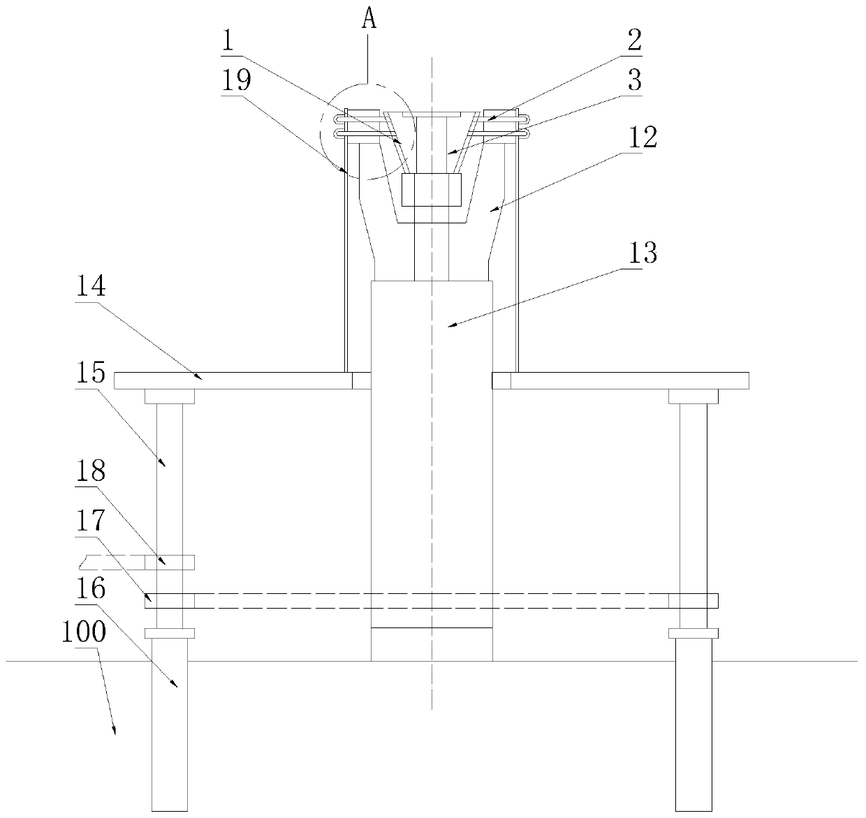
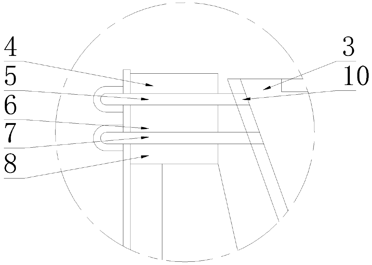
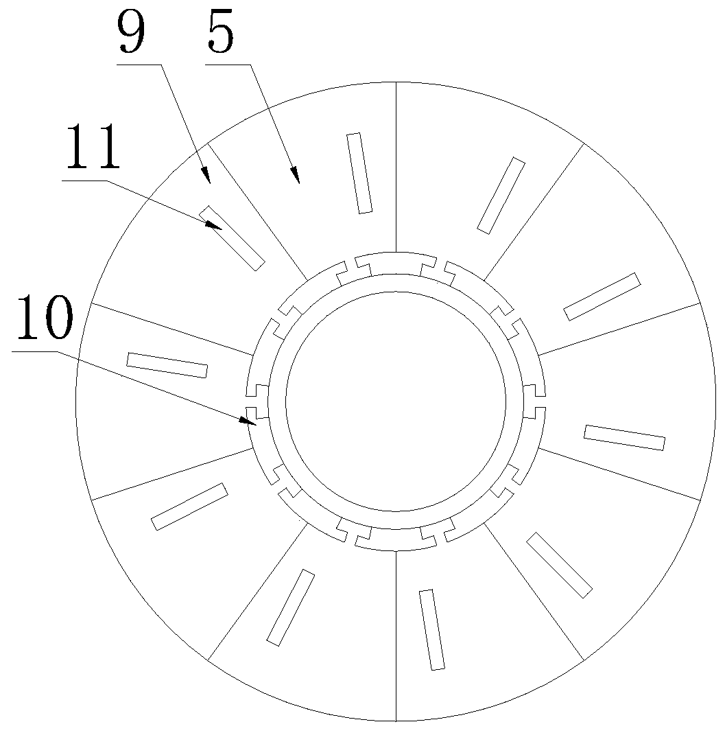
[0029] Such as Figure 1-4 As shown, a bellows automatic forming device includes a bulging device 1 for forming corrugations, and the bulging device 1 includes a die forming mechanism 2 and a conical loading head 3 located at the center of the die forming mechanism 2 The mold forming mechanism 2 includes a pressing plate 4, an upper bulging formwork 5, a splint 6, a lower bulging formwork 7 and a backing plate 8 stacked from top to bottom, and the upper bulging formwork 5 and the lower bulging formwork 7 are composed of The module unit 9 of a plurality of fan rings distributed in an annular array is composed, the inner end of the module unit 9 is provided with a slide block 10, and the outer wall of the conical loading head 3 is provided with a chute arranged in the axial direction, and the slide block 10 embedded in the chute;

[0030] Above-mentioned, the mold unit 9 quantity of last bulging formwork 5 and following bulging formwork 7 is identical, is N, and the angle of ea...

Embodiment 2

[0049] The difference from the first embodiment is that the loading cylinder 13 adopts an adjustable stroke cylinder. The lifting height of the conical loading head 3 can be adjusted by adjusting the stroke of the loading cylinder 13, thereby adjusting the bulging diameters of the upper bulging template 5 and the lower bulging template 7, so as to be suitable for the corrugation forming of tube blanks 19 of various diameters processing.


PUM


Abstract

The invention relates to an automatic corrugated pipe forming device and method. The automatic corrugated pipe forming device comprises an bulging device for forming corrugations, the bulging device comprises a die piece forming mechanism and a conical loading pressing head arranged in the center of the die piece forming mechanism, the die piece forming mechanism comprises a pressing plate, an upper bulging die plate, a clamping plate, a lower bulging die plate and a base plate which are stacked from top to bottom, the upper bulging die plate and the lower bulging die plate each are composed of a plurality of die piece units of a fan ring distributed in an annular array mode, sliding blocks are arranged at the inner ends of the die piece units, a sliding groove which is formed in the axialdirection is formed in the outer wall of the conical loading pressing head, and the sliding blocks are embedded in the sliding groove. According to the automatic corrugated pipe forming device and method, the design of the two bulging die plates is used for filling corrugation breaking points, die pieces do not need to be rotated, the mechanism is simple and more stable, the working efficiency isgreatly improved, and the device and method are worthy of being vigorously popularized.

Description

technical field [0001] The invention belongs to the technical field of bellows forming, and in particular relates to an automatic forming device for bellows. Background technique [0002] The hydraulic processing of metal bellows pipe is a common process method for forming ring bellows with circular, oval, rectangular, track-shaped and other cross-sections. After adjusting the relative position of the mold and the tube blank, pressurize the inner cavity of the tube blank, and then perform mechanical compression along its axial direction, and a corrugated tube with a given length is quickly formed. This is a method of hydroforming called multi-wave one-shot forming. Generally, bellows used as elastic components usually adopt this processing method. But for the corrugated pipe as the main body of the metal hose, this method will not work. Because this kind of bellows requires as long as possible. To this end, people have created another method of hydroforming, that is, sin...

Claims


Application Information

Patent Timeline
IPC IPC(8): B21D15/02B21D37/10
Inventor 王建华王征
Owner ANHUI GAS BELLOWS
Learn More