D-axis current injection-based side converter fault-tolerant control method
A fault-tolerant control and shaft current technology, which is applied in the direction of motor generator control, electronic commutation motor control, control system, etc., can solve the problem that the effect of fault-tolerant control is not optimal, the negative impact of the fault switch tube on the system is not considered, and under-compensation, etc. problem, to achieve the effect of improving the phenomenon of zero-current hooping and improving the effect of fault-tolerant control
- Summary
- Abstract
- Description
- Claims
- Application Information
AI Technical Summary
Problems solved by technology
Method used
Image
Examples
Embodiment 1
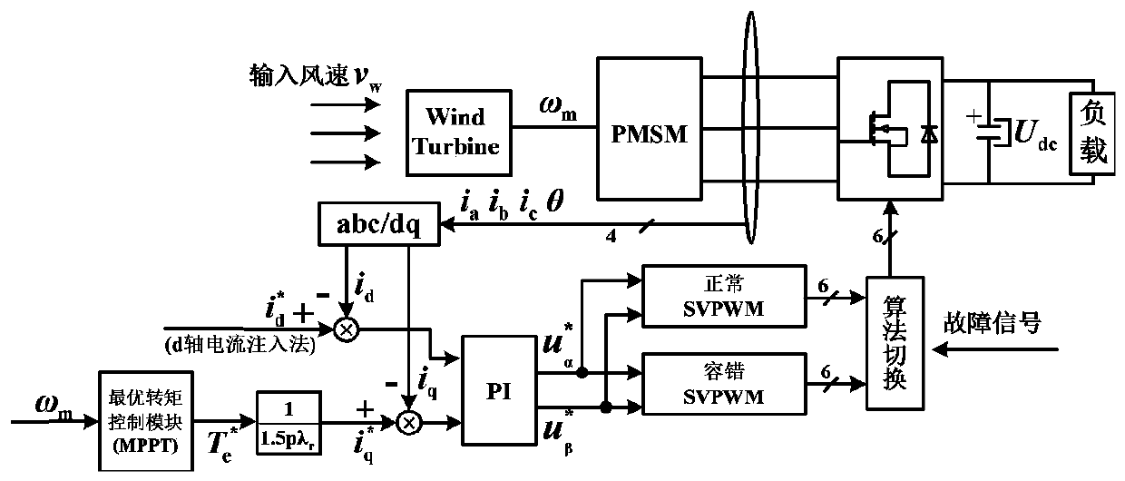
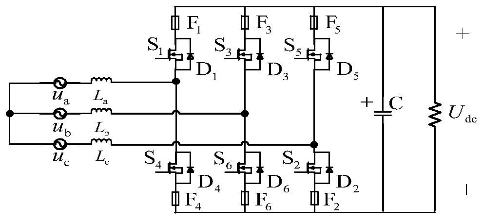
[0160] In this embodiment, the single-tube fault S1 of the machine-side converter of the direct-drive wind power generation system is divided into eight sectors. When a short-circuit fault occurs in the S1 tube, it will be converted into an open circuit fault by the fast fuse. When an open-circuit fault occurs, the d-axis current injection method is explained according to the state analysis of the machine-side converter in the eight-sector division mode under the S1 switching tube fault in Table 16.
[0161] Table 16 Analysis of PWM rectifier eight-sector single-cycle state under S1 switch tube failure
[0162]
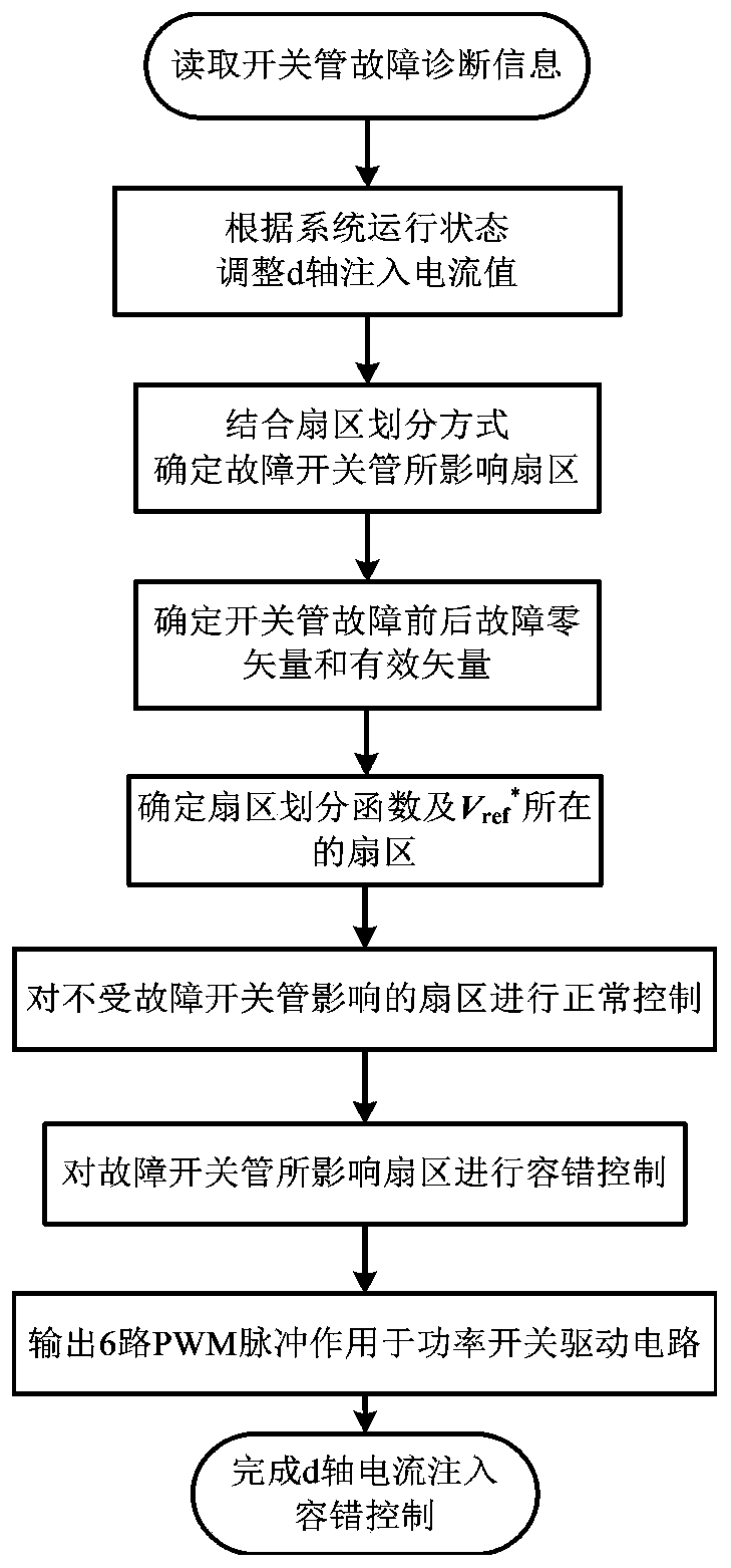
[0163] The schematic diagram of the sector distribution affected by the fault switch tube of the machine-side converter S1 tube fault in the eight-sector division mode is as follows: Figure 6 As shown, when the S1 tube fails, first adjust the d-axis current given value according to the system operating state. Then, for the sectors not affected by the faulty switc...
Embodiment 2
[0165] In this embodiment, the single-tube fault S1 of the machine-side converter of the direct-drive wind power generation system is divided into twelve sectors. When an open-circuit fault occurs in S1, the d-axis current injection fault-tolerant control method is described according to the state analysis of the machine-side converter in the twelve-sector division mode under the fault of the S1 switching tube in Table 17.
[0166] 17 Single-cycle state analysis of 12-sector PWM rectifier under the fault of S1 switching tube
[0167]
[0168]
[0169] The schematic diagram of the sector distribution affected by the fault switch tube of the machine-side converter S1 tube fault in the twelve-sector division mode is as follows: Figure 8 As shown, when the S1 tube fails, first adjust the d-axis current given value according to the system operating state. Then, for the sectors not affected by the faulty switching tube in Table 17, the reference voltage rotation vector is no...
PUM
 Abstract
Description
Claims
Application Information
 - R&D Engineer
- R&D Manager
- IP Professional
- Industry Leading Data Capabilities
- Powerful AI technology
- Patent DNA Extraction
Browse by: Latest US Patents, China's latest patents, Technical Efficacy Thesaurus, Application Domain, Technology Topic, Popular Technical Reports.
© 2024 PatSnap. All rights reserved.Legal|Privacy policy|Modern Slavery Act Transparency Statement|Sitemap|About US| Contact US: help@patsnap.com


