
A lifting device using a real-time movable rigid connection mechanism

A lifting device, rigid connection technology, applied in the direction of antenna support/installation device, retractable unit, folded antenna, etc., can solve the problems of difficult calculation of pre-processing curvature, difficult to guarantee technical status, large processing error, etc. The effect of reducing the statically indeterminate internal force, eliminating the bending moment and reducing the internal force of the structure

Active Publication Date: 2020-04-07
YANSHAN UNIV
View PDF8 Cites 0 Cited by
  • Summary
  • Abstract
  • Description
  • Claims
  • Application Information

AI Technical Summary

Problems solved by technology

Using this method to eliminate heavy-duty stress has a simple mechanism and involves fewer structures, but the pre-processing bending degree is not easy to calculate, there are large processing errors, long-term load will cause creep, and the technical status is difficult to guarantee

Method used


Image

  • A lifting device using a real-time movable rigid connection mechanism
  • A lifting device using a real-time movable rigid connection mechanism
  • A lifting device using a real-time movable rigid connection mechanism

Examples


Embodiment Construction

[0029] The following will clearly and completely describe the technical solutions in the embodiments of the present invention with reference to the accompanying drawings in the embodiments of the present invention. Obviously, the described embodiments are only some, not all, embodiments of the present invention. Based on the embodiments of the present invention, all other embodiments obtained by persons of ordinary skill in the art without making creative efforts belong to the protection scope of the present invention.

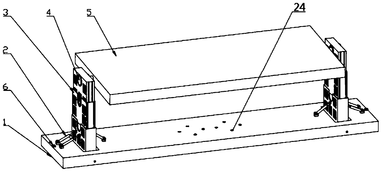
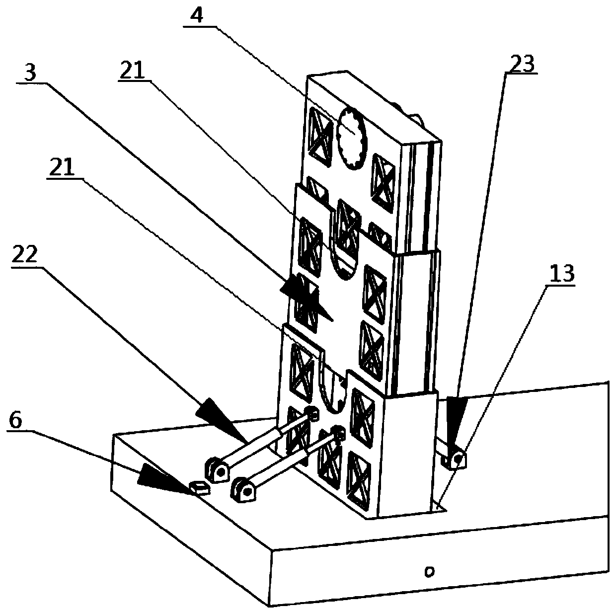
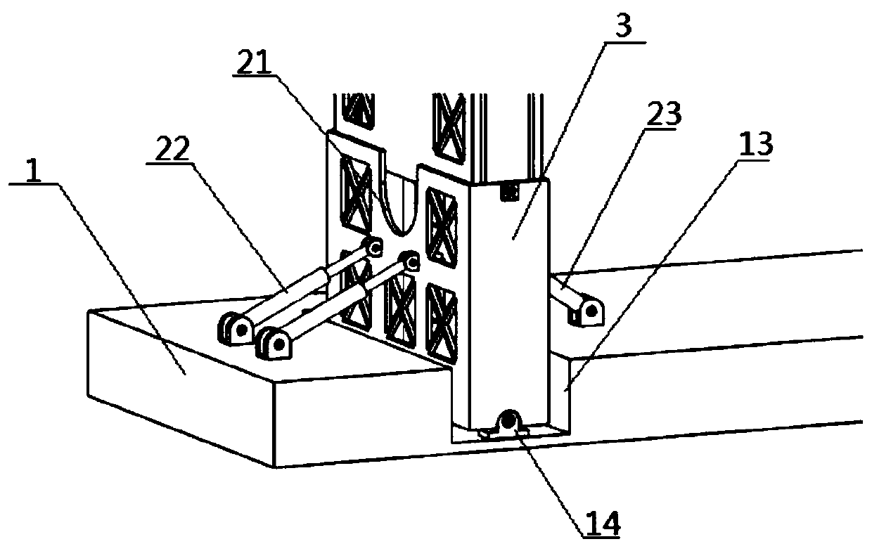
[0030] The purpose of the present invention is to provide a lifting device using a real-time movable rigid connection mechanism to solve the problems in the prior art above, reduce or eliminate the bending moment, enable the lifting system to dynamically maintain a vertical state, and prevent the lifting system from appearing The stuck phenomenon can effectively reduce the super-static internal force of the mechanism system.

[0031] In order to make the above...


PUM


Abstract

The invention discloses a lifting device employing a real-time movable rigid linkage mechanism. The lifting device comprises a working platform, a horizontal sensor, correction systems and a controller, wherein lifting systems are hinged with the working platform and are symmetrically arranged, the bottom of each lifting system is hinged with one end of one of the correction systems, the other endof each correction system is hinged with the working platform, the horizontal sensor is arranged on the working platform and is used for measuring horizontal degree of the working platform, the controller is electrically connected with the horizontal sensor and the correction systems, and the correction systems are used for correcting the lifting systems to be in vertical states. By the lifting device, the lifting systems can be dynamically maintained in the vertical states, the stuck phenomena of the lifting systems are prevented, the indeterminate internal force of a mechanism system is effectively reduced, the structure internal force is reduced, the lifting reliability is ensured, and normal gesture adjustment and working condition running of large-size antenna equipment are met.

Description

technical field [0001] The invention relates to the technical field of lifting of heavy-duty equipment, in particular to a lifting device adopting a real-time movable rigid coupling mechanism. Background technique [0002] With the continuous development and improvement of space technology, heavy-duty antenna equipment that can be used to explore the space field has gradually appeared. Because these equipment need to rise to the calibrated space height before they can adjust their attitude and operate under normal working conditions, and the heavy-duty antenna It will bend the bottom support of the lifting mechanism and cause the guide rail to be stuck, which will affect the normal operation of the lifting mechanism. Therefore, a safe, reliable, and accurately positioned heavy-duty antenna lifting device is required to accurately lift the large antenna equipment to the calibrated height to meet The large antenna equipment performs normal attitude adjustment and working condi...

Claims


Application Information

Patent Timeline
Patent Type & Authority Patents(China)
IPC IPC(8): H01Q1/10H01Q1/12
Inventor 周玉林田宇晟刘毅姚建涛毕宫鑫琦胡金明商涛王若超张泰铭宋彦佐
Owner YANSHAN UNIV
Learn More