A battery detection method, circuit and device

A battery detection and battery technology, applied in the direction of measuring devices, measuring current/voltage, measuring electricity, etc., can solve the problems of unable to detect batteries in batches, and achieve the effect of batch measurement

Active Publication Date: 2021-06-29
BEIJING JINGWEI HIRAIN TECH CO INC
View PDF0 Cites 0 Cited by
  • Summary
  • Abstract
  • Description
  • Claims
  • Application Information

AI Technical Summary

Problems solved by technology

[0003] However, the above-mentioned battery detection scheme is usually used for individual detection of batteries, and cannot be used for batch detection of batteries

Method used


Image

  • A battery detection method, circuit and device
  • A battery detection method, circuit and device
  • A battery detection method, circuit and device

Examples


Embodiment Construction

[0052] The following will clearly and completely describe the technical solutions in the embodiments of the present invention with reference to the accompanying drawings in the embodiments of the present invention. Obviously, the described embodiments are only some, not all, embodiments of the present invention. Based on the embodiments of the present invention, all other embodiments obtained by persons of ordinary skill in the art without making creative efforts belong to the protection scope of the present invention.

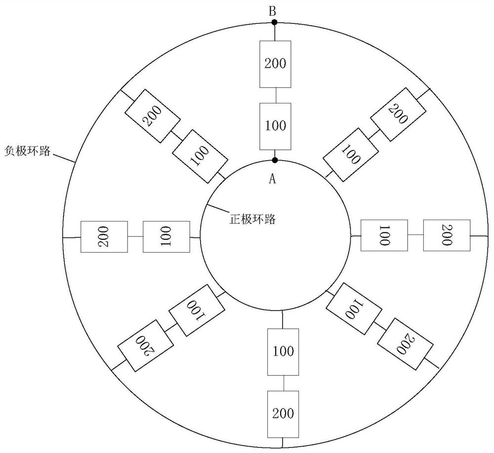
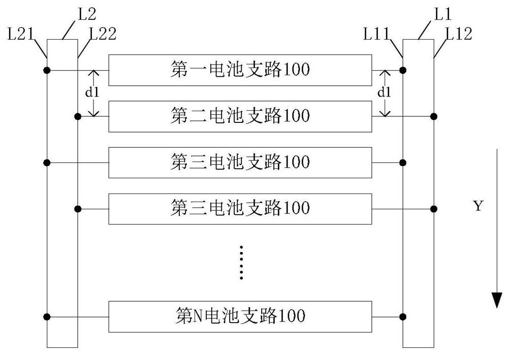
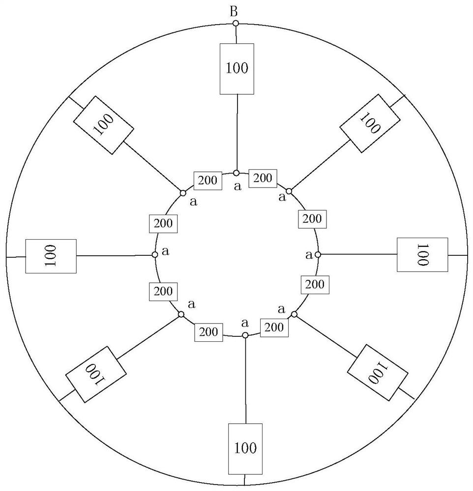
[0053] In order to solve the problem that the battery measurement method in the prior art cannot measure batteries in batches, the present invention discloses a battery detection circuit, see figure 1 , figure 1 It is a schematic topology diagram of a battery detection circuit disclosed in an embodiment of the present invention, and the battery detection circuit includes: a plurality of battery branches 100 and a current collector 200 .

[0054] Wherein, the ...


PUM


Abstract

The invention provides a battery detection method, circuit and device. The circuit includes: a plurality of battery branches connected in parallel; the first end of each battery branch is electrically connected to the first node, and the second end of each battery branch is electrically connected to the first node. The two nodes are electrically connected, and each battery branch is provided with a battery to be tested, and one of the battery branches is recorded as a reference branch, and the leakage current of the battery to be tested in the reference branch is a known quantity; The current collector is used to directly or indirectly detect the current in each battery branch circuit, and provides a circuit basis for batch measurement of the battery to be tested.

Description

technical field [0001] The invention relates to the technical field of electronic circuits, in particular to a battery detection method, circuit and device. Background technique [0002] In the existing battery leakage detection scheme, the battery leakage is usually detected by using a symmetrical ring circuit topology and an internal short circuit identification method based on a symmetrical ring circuit topology. During the detection process, by comparing the characteristic values ​​of each battery, To determine that a certain battery is an internal short circuit battery. Wherein, the characteristic value of the battery here may be the correlation coefficient between the actual current value of each battery and the theoretical current value, or the measured current proportional relationship of each battery, etc. [0003] However, the above-mentioned battery testing scheme is usually used to test the batteries individually, and cannot perform batch testing on the batterie...

Claims


Application Information

Patent Timeline
Patent Type & Authority Patents(China)
IPC IPC(8): G01R31/385G01R19/10
Inventor 张明轩
Owner BEIJING JINGWEI HIRAIN TECH CO INC
Why Eureka
Try Eureka