Frame type decoration structure and mounting method thereof

A frame-type and frame-based technology, which is applied in the direction of building components, building structures, covering/lining, etc., can solve the problems that workers are difficult to adjust the support parts of the board, the flatness is not ideal, and the installation efficiency is low, so as to achieve the overall stability of the decoration structure , Improve the efficiency of positioning and installation, and improve the effect of construction efficiency

Active Publication Date: 2019-06-21
佛山市大业工业设计有限公司
View PDF9 Cites 0 Cited by
  • Summary
  • Abstract
  • Description
  • Claims
  • Application Information

AI Technical Summary

Problems solved by technology

[0005] (1) The ground structure is laid directly with boards, and it is difficult for workers to adjust the supporting parts under the boards, so it is difficult to ensure that the ground structure is set horizontally; when the boards need to adjust the levelness, workers need to repeatedly disassemble and assemble the boards to adjust the supporting parts , which is not conducive to the improvement of construction efficiency; and because each panel is supported by an independent support component, each panel needs to be adjusted separately for levelness, the levelness of each panel cannot be guaranteed to be completely uniform, and there may be problems at the joints of the panels. Uneven, unsatisfactory flatness;
[0006] (2) Since the wall and ground of the indoor space are often uneven, the existing ground structure cannot fully utilize the wall and ground of the indoor space for positioning and fixing, which affects the stability of the decoration structure, reduces the user experience and poses a threat to safety. Hidden danger;
[0007] (3) Due to the unevenness of the wall surface in the indoor space, the middle skeleton cannot fit the wall so that the wall faces the middle skeleton to form a position; The water supply pipes and wires pass through the space, and the middle frame and the wall cannot be fitted together to realize the positioning of the middle frame; therefore, it is necessary to use parts to locate the center frame, but the installation of the existing positioning structure is very inconvenient and the installation efficiency is low;
[0008] (4) When used in bathrooms and other occasions where sewage is produced, there is a lack of measures to prevent water seepage, resulting in sewage easily flowing into the space below the floor panels to form stagnant water, which is easy to breed mosquitoes and bacteria, resulting in poor sanitation; stagnant water may flow into the lower residents The room caused problems such as water leakage in the rooms of the residents on the lower floor

Method used


Image

  • Frame type decoration structure and mounting method thereof
  • Frame type decoration structure and mounting method thereof
  • Frame type decoration structure and mounting method thereof

Examples


Embodiment 1

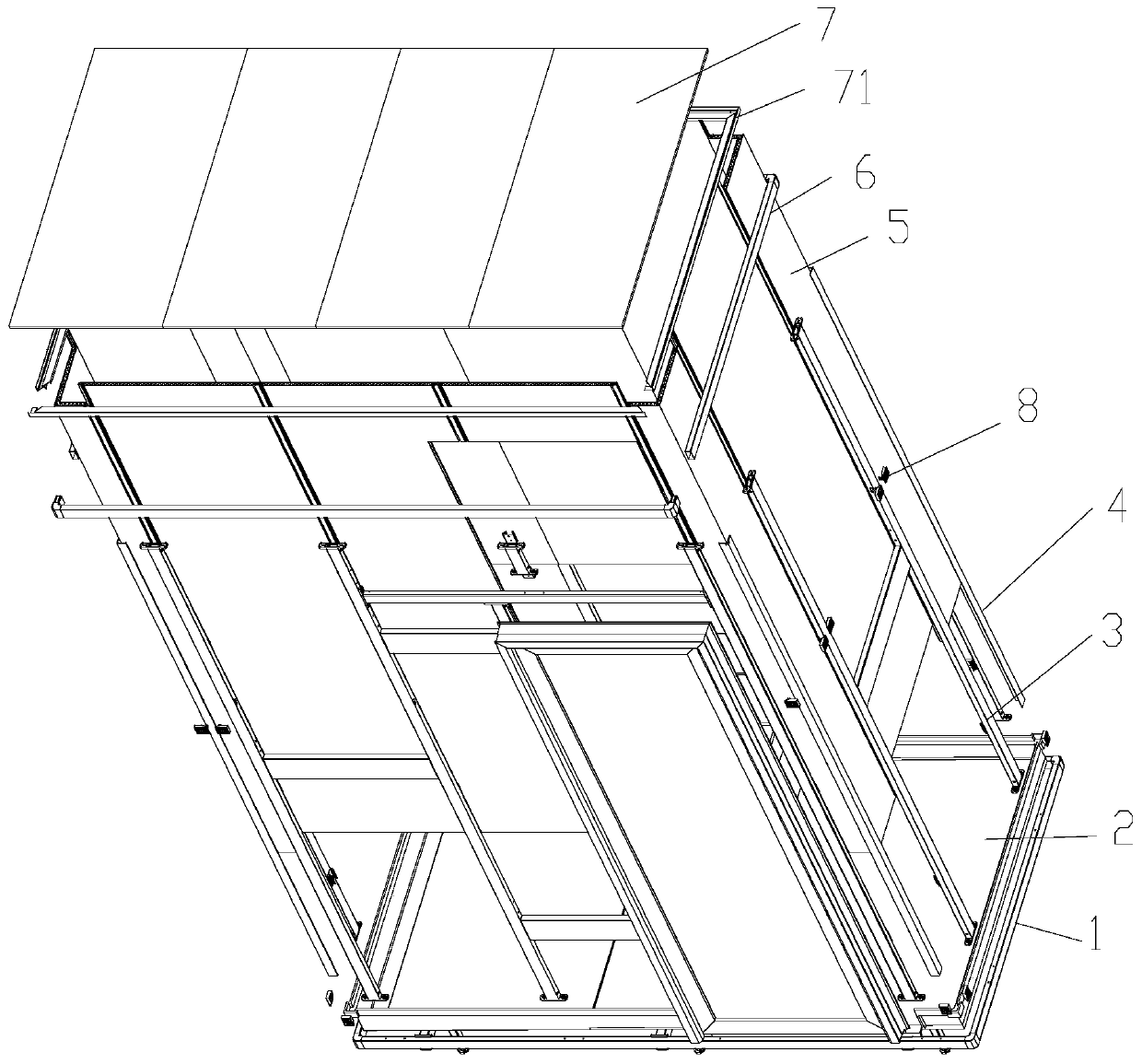
[0086] This embodiment is a frame type decoration structure, which is set in the indoor space, and its structure is as follows: Figure 1 to Figure 20 Shown; Including ground structure, wall structure, ceiling 7 and upper frame 6.

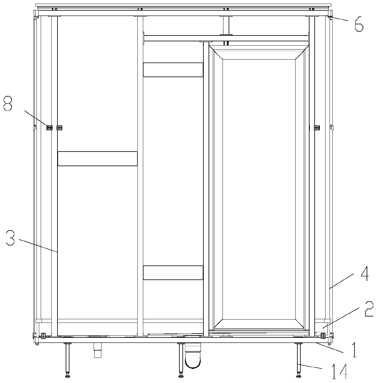
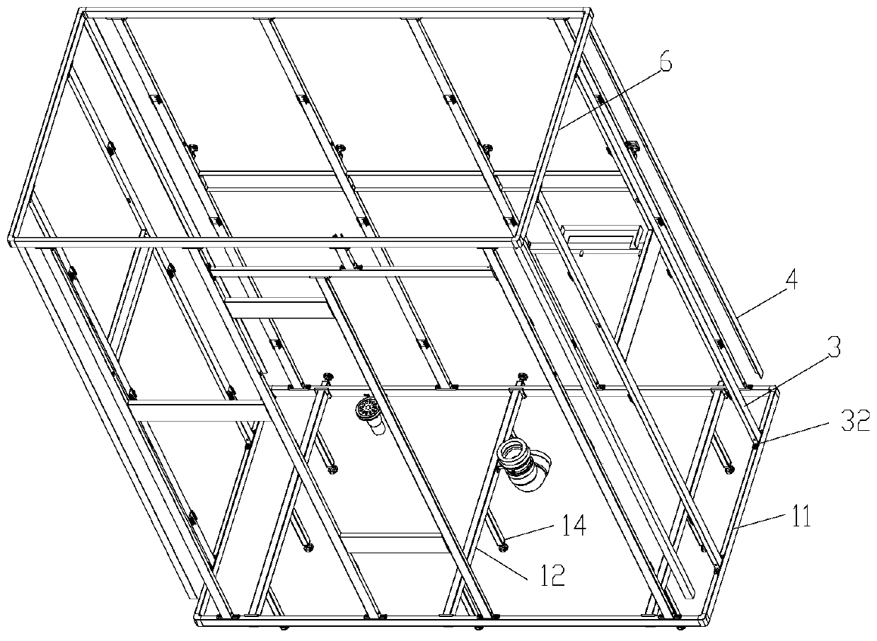
[0087] The ground structure includes a floor support bracket 1 , adjustment feet 13 , lifting feet 14 and floor panels 2 . The floor support frame 1 is set on the solid ground through the lifting feet 14; the floor support frame 1 is provided with adjustment feet 13; the horizontal direction positioning of the floor support frame 1 is realized through the support of the adjustment feet 13 and the solid wall. In practical application, it is also possible that the floor support bracket 1 is provided with adjustment feet 13 above both sides. The floor panel 2 is supported on the floor support frame 1 .

[0088] The wall structure includes several middle frames 3, corner frames 4, upper frames 6 and wall panels 5; the corner frames 4 are arranged on ...

Embodiment 2

[0121] The difference between the frame decoration structure of this embodiment and Embodiment 1 is that: in this embodiment, if Figure 21 to Figure 23 As shown, the lower part of the floor panel 2 is fixedly provided with a reinforcement frame 29; the reinforcement frame is arranged on the floor support frame 1, and the reinforcement frame 29 is provided with a frame connection part 291, and the frame connection part 291 and the floor support frame 1 adopt screws and bolts and other connectors. The rest of the structure of this embodiment is the same as that of Embodiment 1.

Embodiment 3

[0123] The difference between the frame decoration structure of this embodiment and the first embodiment is that: in this embodiment, the decoration structure is not provided with a floor drain assembly, and the floor panel is not provided with a floor drain. The rest of the structure of this embodiment is the same as that of Embodiment 1.


PUM


Abstract

The invention provides a frame type decoration structure. The frame type decoration structure is characterized by comprising a ground structure and a wall surface structure. The ground structure comprises a floor supporting frame, lifting feet and a ground panel piece. The floor bearing frame is arranged on the solid ground through the lifting feet. The floor panel piece is supported on the floorsupporting frame. The wall surface structure comprises a plurality of middle frameworks, corner frameworks, an upper edge framework and wall plates; the corner skeletons are arranged on bending positions of the ground panel piece; each middle framework is arranged between adjacent corner frameworks; each middle framework is arranged on the floor supporting frame or the floor panel piece; the topsof the middle frameworks and the tops of the corner frameworks are connected with the upper edge frame; and the wall plates are fixedly connected with the middle frameworks or the corner frameworks, or the wall plates are simultaneously fixedly connected with the middle frameworks and the corner frameworks. The decoration structure can be conveniently adjusted and constructed by workers, and it isensured that the ground structure is horizontally arranged. The invention further provides an installation method of the decoration structure, the installation method is simple and convenient to install, and the installation efficiency can be improved.

Description

technical field [0001] The invention relates to the technical field of decoration structures, more specifically, to a frame-type decoration structure and an installation method thereof. Background technique [0002] The traditional decoration method first uses cement, sandstone, lime and other materials to paint, and then paints or lays tiles and tiles wallpaper; the construction time is long, consumes a lot of materials, and the decoration cost is high. And when it is necessary to redecorate, the workload required to remove the original decoration materials is very large, further increasing the decoration cost. [0003] In order to quickly carry out decoration and layout, there is currently a modular decoration method in which the interior space is modularized to construct an inner space with a decoration effect in the interior space; it can effectively speed up the construction progress and save labor costs, and is also convenient Replacement decoration. [0004] However...

Claims


Application Information

Patent Timeline
Patent Type & Authority Applications(China)
IPC IPC(8): E04F15/024E04F13/072E04F13/08E04F13/22E04F13/24E04B9/06
Inventor 盛光润汪长安
Owner 佛山市大业工业设计有限公司
Why Eureka
Try Eureka