A textile fiber press molding device

A compression molding and textile fiber technology, which is applied in the field of textile fiber compression molding device and fiber cotton manufacturing process, can solve the problems of reducing the utilization rate of fiber cotton material, restricting the shape of fiber cotton, and long processing process, so as to improve the material utilization rate , reduce the amount of waste, improve the effect of utilization

Active Publication Date: 2020-10-02
武汉奥利维亚科技有限公司
View PDF13 Cites 0 Cited by
  • Summary
  • Abstract
  • Description
  • Claims
  • Application Information

AI Technical Summary

Problems solved by technology

[0002] At present, fiber cotton refers to a kind of shaped cotton made of various textile fibers. Textile fibers include natural fibers and chemical fibers. Most of the existing manufacturing processes are to first open the textile fibers through raw materials and card them into a net. Various processes are then carried out, such as warp and weft weaving, layer-by-layer superposition, vertical / horizontal web laying or their combination, and finally drying and cooling to obtain shaped cotton. Not only the processing process is long and the process is numerous, but also the shape of fiber cotton is greatly limited , leading to the production of follow-up products, it is necessary to carry out more shape changes on the obtained fiber cotton, such as cutting, resulting in a large amount of waste and reducing the material utilization rate of fiber cotton

Method used


Image

  • A textile fiber press molding device
  • A textile fiber press molding device
  • A textile fiber press molding device

Examples


Embodiment 1

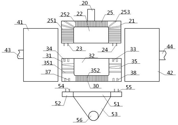
[0055] see figure 1 - Figure 12, a kind of textile fiber pressing molding device, comprises upper mold 2 and lower mold 3 arranged up and down, and hollow outer sleeve 4, and this outer sleeve 4 is set on the outside of upper mold 2, lower mold 3, and outer sleeve 4 The height is greater than the sum of the heights of the upper mold 2 and the lower mold 3, and the width of the inner wall of the outer sleeve 4 is greater than the width of the upper mold 2 and the lower mold 3; Mold cavity 22, lower mold 3 comprises lower mold body 31 and the lower mold cavity 32 that its inside offers, and upper mold cavity 22, lower mold cavity 32 butt up and down to form a molding cavity 1; The top surface of described upper mold body 21 and The lower pressing shaft 20 is connected, and the bottom surface of the upper mold body 21 is provided with a concentric upper inner slide rail 23 and an upper outer slide rail 24 around the position of the upper mold cavity 22. The upper inner slide ra...

Embodiment 2

[0057] Basic content is the same as embodiment 1, the difference is:

[0058] The top surface of the lower mold body 31 is sandwiched between the lower inner chute 33 and the lower outer chute 34. A concave partition groove 36 is provided. The partition groove 36 is an annular structure, and the partition groove 36 includes The partition straight cavity 361 , the partition inner concave cavity 362 , and the partition bottom cavity 363 are connected in sequence from top to bottom, and the widths of the partition straight cavity 361 and the partition bottom cavity 363 are greater than the maximum width of the partition inner concave cavity 362 .

Embodiment 3

[0060] Basic content is the same as embodiment 1, the difference is:

[0061] The air injection device 5 includes an air outlet 51, an outer ring disk 52 and an air containment cover 53. The air containment cover 53 is a conical structure with a wide top and a narrow bottom. The bottom end of the air containment cover 53 is connected with the air intake pipe 56 , the top of the air containment cover 53 is connected to the air outlet 51, the outer ring of the air outlet 51 is provided with an outer ring disk 52, and the top surface of the outer ring disk 52 is provided with concentric inner air around the air outlet 51. The slide rail 54, the external air slide rail 55, the internal air slide rail 54, and the external air slide rail 55 are all ring structures, and the bottom surface of the lower die body 31 is provided with concentric air slide rails around the air intake area 30. Groove 37, air outer chute 38, air inner chute 37, air outer chute 38 are all annular structures, ...


PUM


Abstract

A textile fiber pressing forming device comprises an upper die, a lower die and an outer sleeve. The upper die comprises an upper die body and an upper die cavity. The lower die comprises a lower diebody and a lower die cavity. The upper die cavity and the lower die cavity are in up-down butt joint to form a forming cavity. The height of the outer sleeve is larger than the sum of the height of the upper / lower die. The part, around the upper die cavity, of the bottom face of the upper die body is provided with a concentric upper inner / outer sliding rail. The part, around the lower die cavity,of the top face of the lower die body is provided with a concentric lower inner / outer sliding groove. The lower inner sliding groove is in sliding fit with an upper inner sliding rail inserted in thelower inner sliding groove. The lower outer sliding groove is in sliding fit with an upper outer sliding rail inserted in the lower outer sliding groove. The upper die body is internally provided witha plurality of upper ventilation ways communicating with the upper die cavity. The lower die body is internally provided with a plurality of lower ventilation ways communicating with the lower die cavity. The outer ends of the lower ventilation ways communicate with an air outlet of an air spraying device through the air inlet area. According to the design, the shape of fiber cotton is not limited, the material utilization rate is improved, adjustability is high, and product interior uniformity can be improved.

Description

technical field [0001] The invention relates to a fiber cotton manufacturing process, which belongs to the field of textile machinery, in particular to a textile fiber pressing and forming device. Background technique [0002] At present, fiber cotton refers to a kind of shaped cotton made of various textile fibers. Textile fibers include natural fibers and chemical fibers. Most of the existing manufacturing processes are to first open the textile fibers through raw materials and card them into a net. Various processing is then carried out, such as warp and weft weaving, layer-by-layer superposition, vertical / horizontal web laying or their combination, and finally drying and cooling to obtain shaped cotton. Not only the processing process is long and the process is numerous, but also the shape of fiber cotton is greatly limited , leading to the production of follow-up products, it is necessary to carry out more shape changes to the obtained fiber cotton, such as cutting, the...

Claims


Application Information

Patent Timeline
Patent Type & Authority Patents(China)
IPC IPC(8): B30B15/02B30B15/34
Inventor 张智明王佳伟徐巧梅顺齐姬巧玲肖人彬
Owner 武汉奥利维亚科技有限公司
Why Eureka
Try Eureka