
Radar data transmission device and radar system

A technology for transmitting device and radar data, applied in the field of radar, can solve the problems of increasing the cost of the radar system, increasing the complexity of the radar system, etc., and achieve the effect of reducing the complexity and reducing the cost.

Pending Publication Date: 2019-06-18
CALTERAH SEMICON TECH SHANGHAI CO LTD
View PDF0 Cites 1 Cited by
  • Summary
  • Abstract
  • Description
  • Claims
  • Application Information

AI Technical Summary

Problems solved by technology

In practical applications, it is necessary to introduce an additional clock signal chip for data transmission between the radar terminal device side and the processing terminal, which will not only increase the cost of the radar system, but also increase the complexity of the radar system

Method used


Image

  • Radar data transmission device and radar system
  • Radar data transmission device and radar system
  • Radar data transmission device and radar system

Examples


Embodiment Construction

[0022] Hereinafter, the present invention will be described in more detail with reference to the accompanying drawings. In the various figures, identical elements are indicated with similar reference numerals. For the sake of clarity, various parts in the drawings have not been drawn to scale. Also, some well-known parts may not be shown in the drawings.

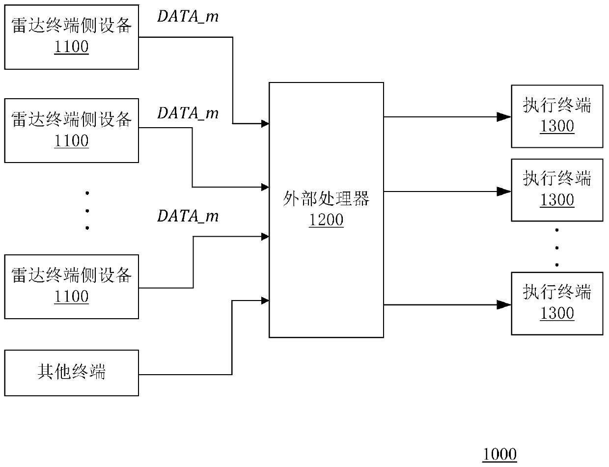
[0023] figure 1 A schematic block diagram of a radar system of an embodiment of the invention is shown.

[0024] like figure 1 As shown, the radar system 1000 in the embodiment of the present invention includes at least one radar terminal-side device 1100 and an external processor 1200 . Each radar terminal-side device 1100 generates radar data according to received radar signals; the external processor 1200 receives the radar data DATA_m provided by each radar terminal-side device 1100 , and performs post-processing on the radar data DATA_m to obtain corresponding received data.

[0025] The data processing link (also ...


PUM


Abstract

The invention belongs to the field of radar technologies and relates to a radar data transmission device and a radar system. The transmission device comprises a radar transceiver and a data transmitter; the radar transceiver is used for generating frequency sweep signals, wherein the frequency sweep signals have pulse transmission intervals and waiting intervals in the time domain, wherein the waiting intervals are used for isolating adjacent pulse transmission intervals; the data transmitter is connected with the radar transceiver; the radar transceiver is used for providing clock signals tothe data transmitter in the waiting intervals; and the data transmitter performs serial transmission on radar data based on clock signals. With the radar data transmission device and the radar systemof the present invention adopted, the high-speed transmission of multi-channel data can be realized with no additional clock circuits required. The radar data transmission device has the advantages ofsimple structure and low cost.

Description

technical field [0001] The present invention relates to the technical field of radar, and more specifically, to a radar data transmission device and a radar system. Background technique [0002] At present, miniaturization and thin terminal have gradually become the design trend of radar system. Thin terminal design means that only a small amount of signal processing or no signal processing is performed on the radar terminal equipment side, but most of the signal processing and data fusion processes are placed in the processing terminal of the radar system (such as the central processing unit, domain processor, etc.), the advantage of this design is that it can improve the performance and efficiency of the radar system. In practical applications, it is necessary to introduce an additional clock signal chip for data transmission between the radar terminal device side and the processing terminal, which will not only increase the cost of the radar system, but also increase the...

Claims


Application Information

Patent Timeline
IPC IPC(8): G01S7/00
Inventor 刘洪泉
Owner CALTERAH SEMICON TECH SHANGHAI CO LTD
Learn More