
An orderly winding device for textile ropes used in textile workshops

A winding device and workshop technology, applied in the direction of transportation and packaging, thin material handling, and delivery of filamentous materials, etc., can solve the problems of cumbersome sorting, waste of human resources, and poor winding effect, so as to save human resources and improve Reminder timeliness, improve the effect of winding effect

Active Publication Date: 2021-04-02
李向阳
View PDF7 Cites 0 Cited by
  • Summary
  • Abstract
  • Description
  • Claims
  • Application Information

AI Technical Summary

Problems solved by technology

[0003] In the prior art, the existing textile rope winding device has a poor winding effect. After the textile rope is produced, it often needs to be wound by the winding device. However, the textile rope is easily piled up during the winding process, resulting in The winding of the rope is messy, and the follow-up arrangement is relatively cumbersome, and the winding of the textile rope is not tight enough, and the textile rope is easy to slip off from the bobbin, which is very confusing. At the same time, the existing textile rope winding device has no warning function, and the textile rope winding device During rewinding, when the reel is rewinding more textile ropes, the staff cannot be reminded to replace the reel, so manual real-time care is often required, which wastes a lot of human resources. The existing textile rope rewinding The function of the device is relatively single, and now there is an urgent need for a textile rope orderly winding device for textile workshops to solve the above problems

Method used


Image

  • An orderly winding device for textile ropes used in textile workshops
  • An orderly winding device for textile ropes used in textile workshops
  • An orderly winding device for textile ropes used in textile workshops

Examples


Embodiment Construction

[0023] In order to make the technical means, creative features, goals and effects achieved by the present invention easy to understand, the present invention will be further described below in conjunction with specific embodiments.

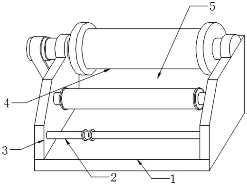
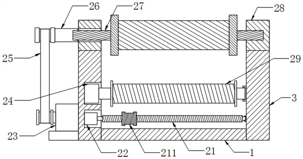
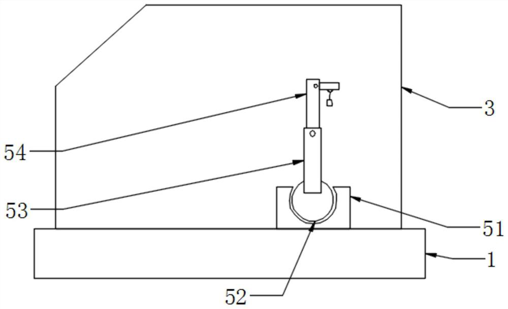
[0024] A textile rope orderly winding device for textile workshops, please refer to Figure 1-Figure 5 , including a base plate 1, a wire take-up mechanism 2, a support plate 3, a bobbin 4 and a warning mechanism 5, and is characterized in that: a support plate 3 is installed on the left and right sides of the upper end surface of the bottom plate 1, and a bobbin is installed in the middle of the support plate 3 4. The wire take-up mechanism 2 is arranged on the upper side of the bottom plate 1, and the warning mechanism 5 is arranged on the upper end of the bottom plate 1 facing the downstream side of the wire release. Three 24, belt 25, bearing 26, rotating shaft 27, arc seat 28 and auxiliary roller 29, warning mechanism 5 comprises limit seat 5...


PUM


Abstract

The invention provides an ordered rolling device of a textile rope for a textile workshop. The ordered rolling device comprises a screw, a rope guide wheel, a motor I, a motor II, a motor III, a limiting seat, a rotating ball, a folding rod I, a folding rod II, a connecting rope and a bell, wherein the motor I is assembled at the left side in a support plate, the screw is mounted at the right sideof the motor I, the rope guide wheel is mounted on the annular side surface of the screw, the motor III is assembled at the upper side of the motor I, and the motor II is assembled at the lower sideof the left end surface of the support plate. The design solves the problem that the rolling effect of the original textile rope rolling device is poor. The rotating ball is mounted in the limiting seat, the folding rod I is mounted at the upper side in the support rod, the folding rod II is mounted at the upper side of the right end surface of the folding rod I, the connecting rope is arranged atthe lower side of the folding rod II, and the bell is suspended at the lower side of the connecting rope. The design solves the problem that the original textile rope rolling device dopes not have awarning function. Compared with the prior art, the device has the advantages of reasonable structure, ordered rolling, timely prompt and complete functions.

Description

technical field [0001] The invention relates to a textile rope orderly winding device for a textile workshop, which belongs to the technical field of textile machinery and equipment. Background technique [0002] The original meaning of textile is taken from the general term of spinning and weaving, but with the continuous development and improvement of the textile knowledge system and subject system, especially after the emergence of non-woven textile materials and three-dimensional composite weaving technologies, the current textile is not only a traditional Hand spinning and weaving also include garment textiles produced by non-woven technology, modern three-dimensional weaving technology, modern electrostatic nano-netting technology, etc. Therefore, modern textile refers to the multi-scale structure processing of a fiber or fiber aggregate technology. Ancient Chinese textile and printing and dyeing technology has a very long history. As early as the primitive society, t...

Claims


Application Information

Patent Timeline
Patent Type & Authority Patents(China)
IPC IPC(8): B65H54/553B65H54/28B65H54/72B65H57/14B65H67/04
Inventor 张国际曹本胜刘尚斌
Owner 李向阳
Learn More