A poultry feed breaking and pulverizing system
A crushing system and feed technology, which is applied in feed, grain processing, food science, etc., can solve problems such as uneven mixing, and achieve the effect of good continuity and high processing efficiency
- Summary
- Abstract
- Description
- Claims
- Application Information
AI Technical Summary
Problems solved by technology
Method used
Image
Examples
specific Embodiment approach 1
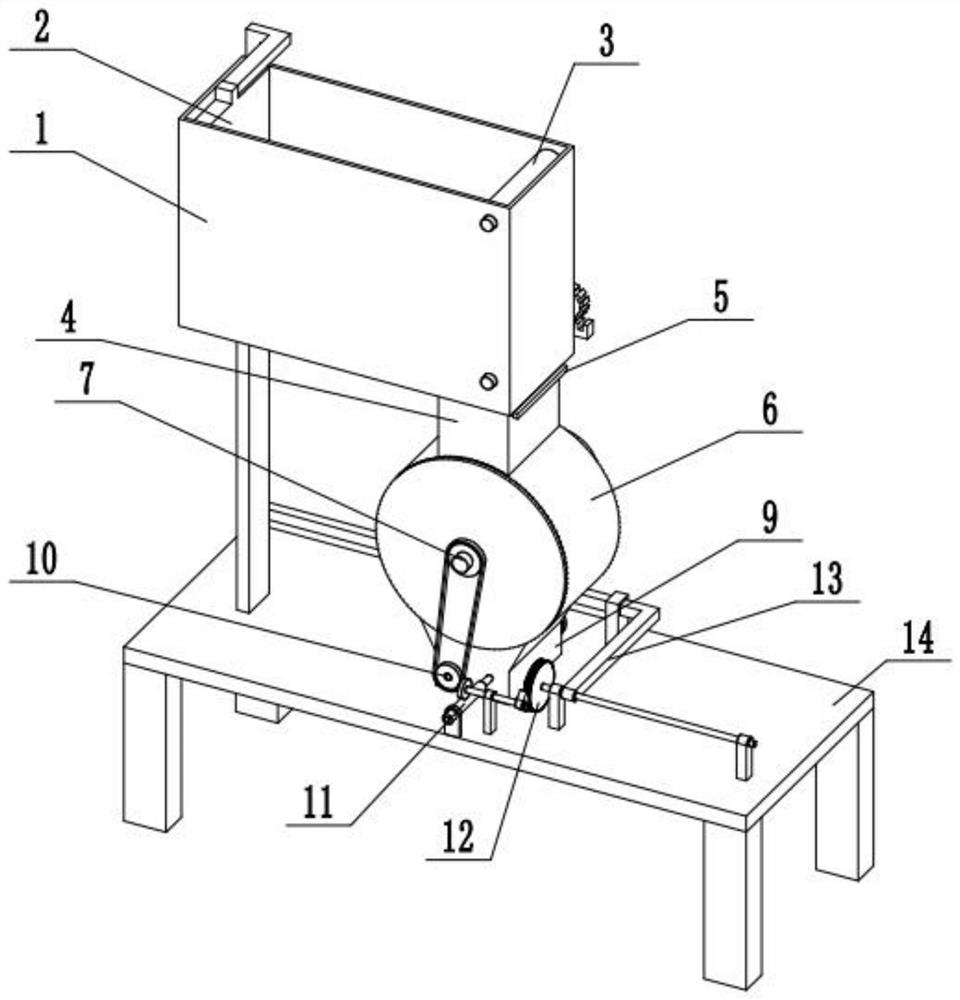
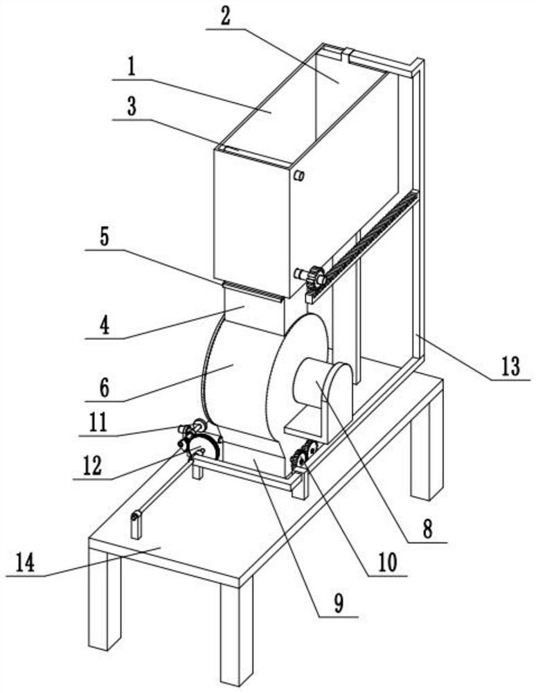
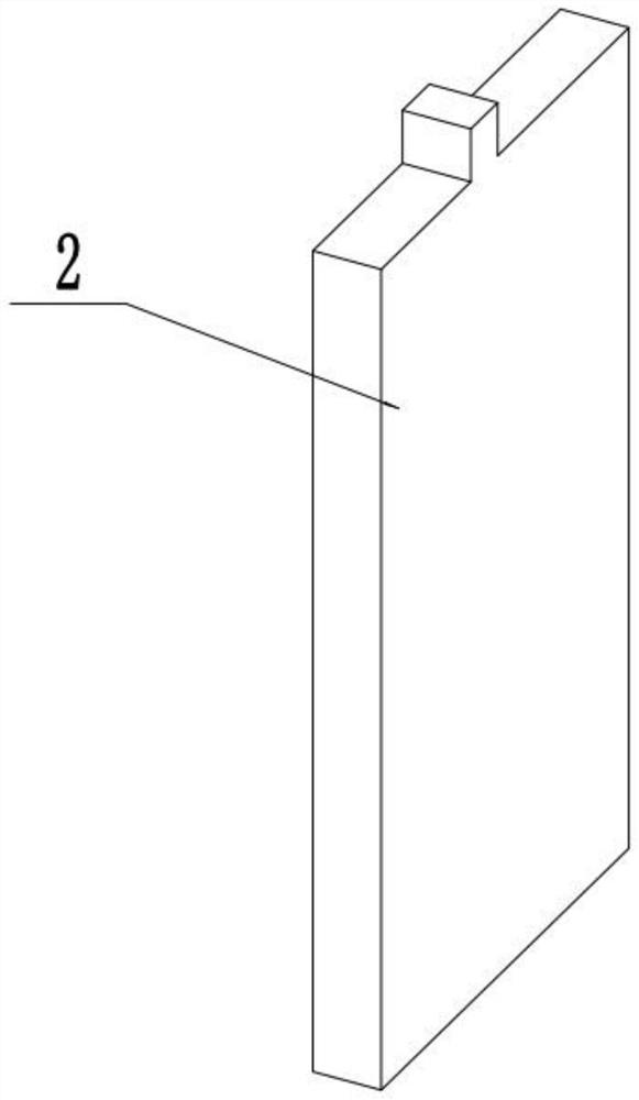
[0029] Such as Figure 1-10 As shown, a poultry feed breaking and crushing system includes a feeding box 1, a pushing plate 2, a feeding anti-blocking belt 3, a blanking box 4, a control panel 5, a breaking box 6, a breaking mechanism 7, and a servo motor 8. Crushing box 9, crushing mechanism 10, transmission wheel 11, linkage wheel 12, sliding connecting rod 13 and frame 14, the feeding box 1, blanking box 4, breaking box 6 and crushing box 9 are from top to bottom Fixedly connected in turn; the feeding box 1 is fixedly connected to the frame 14 through a support plate; the side wall of the crushing box 9 is fixedly connected to the frame 14; the pushing plate 2 is slidingly fitted and connected to the inside of the feeding box 1 One end of the feeding anti-blocking belt 3 is rotatably connected to the other end inside the feeding box 1, and the feeding anti-blocking belt 3 is arranged directly above the blanking box 4; On the side; the dispersing mechanism 7 is rotated and ...
specific Embodiment approach 2
[0031] Such as Figure 1-10As shown, the conveying anti-blocking belt 3 includes a conveying belt body 3-1, a driving axle 3-2, a driven axle 3-3, a roller 3-4, a short shaft 3-5 and a rotating gear 3-6; The driving wheel shaft 3-2 is rotatably connected to the lower end of the feeding box 1, and the driven wheel shaft 3-3 is rotatably connected to the upper end of the feeding box 1; the driving wheel shaft 3-2 and the driven wheel shaft 3-3 are fixedly connected to the roller 3 -4, the two rollers 3-4 are connected through the transmission belt body 3-1; the driving wheel shaft 3-2 is connected to the short shaft 3-5 through a coupling; the short shaft 3-5 is fixed The rotating gear 3-6 is connected; the sliding link 13 is meshed with the rotating gear 3-6 for transmission. When the sliding connecting rod 13 moves to the right, it can drive the rotating gear 3-6 to rotate counterclockwise. When the rotating gear 3-6 rotates counterclockwise, it can drive the driving wheel sh...
specific Embodiment approach 3
[0033] Such as Figure 1-10 As shown, the dispersing mechanism 7 includes a central shaft 7-1, a rotating tube 7-2, a dispersing rod 7-3 and a driving sprocket 7-4; the two ends of the central shaft 7-1 are respectively rotated and connected At both ends of the box 6, one end of the central shaft 7-1 is connected to the output shaft of the servo motor 8 through a coupling, and the other end of the central shaft 7-1 is fixedly connected to the driving sprocket 7-4; 7-4 is connected to the crushing mechanism 10 through a chain drive; the rotating tube 7-2 is fixedly connected to the middle end of the central axis 7-1, and the tube surface of the rotating tube 7-2 is uniformly surrounded and fixedly connected to multiple breaking rods 7- 3; the rotating pipe 7-2 and the breaking rod 7-3 are all rotated and fitted in the inside of the breaking box 6.
[0034] When the described breaking mechanism 7 is working, the output shaft of the servo motor 8 can drive the central shaft 7-1 ...
PUM
 Abstract
Description
Claims
Application Information
 - R&D Engineer
- R&D Manager
- IP Professional
- Industry Leading Data Capabilities
- Powerful AI technology
- Patent DNA Extraction
Browse by: Latest US Patents, China's latest patents, Technical Efficacy Thesaurus, Application Domain, Technology Topic, Popular Technical Reports.
© 2024 PatSnap. All rights reserved.Legal|Privacy policy|Modern Slavery Act Transparency Statement|Sitemap|About US| Contact US: help@patsnap.com


