
Elastic wave device with sub-wavelength thick piezoelectric layer

A technology of elastic wave and piezoelectric layer, applied in piezoelectric/electrostrictive/magnetostrictive devices, electrical components, circuits, etc.

Inactive Publication Date: 2019-06-14
SKYWORKS SOLUTIONS INC
View PDF6 Cites 9 Cited by
  • Summary
  • Abstract
  • Description
  • Claims
  • Application Information

AI Technical Summary

Problems solved by technology

Designing surface acoustic wave resonators that meet or exceed the design specifications of such RF systems can be challenging

Method used


Image

  • Elastic wave device with sub-wavelength thick piezoelectric layer
  • Elastic wave device with sub-wavelength thick piezoelectric layer
  • Elastic wave device with sub-wavelength thick piezoelectric layer

Examples


Embodiment Construction

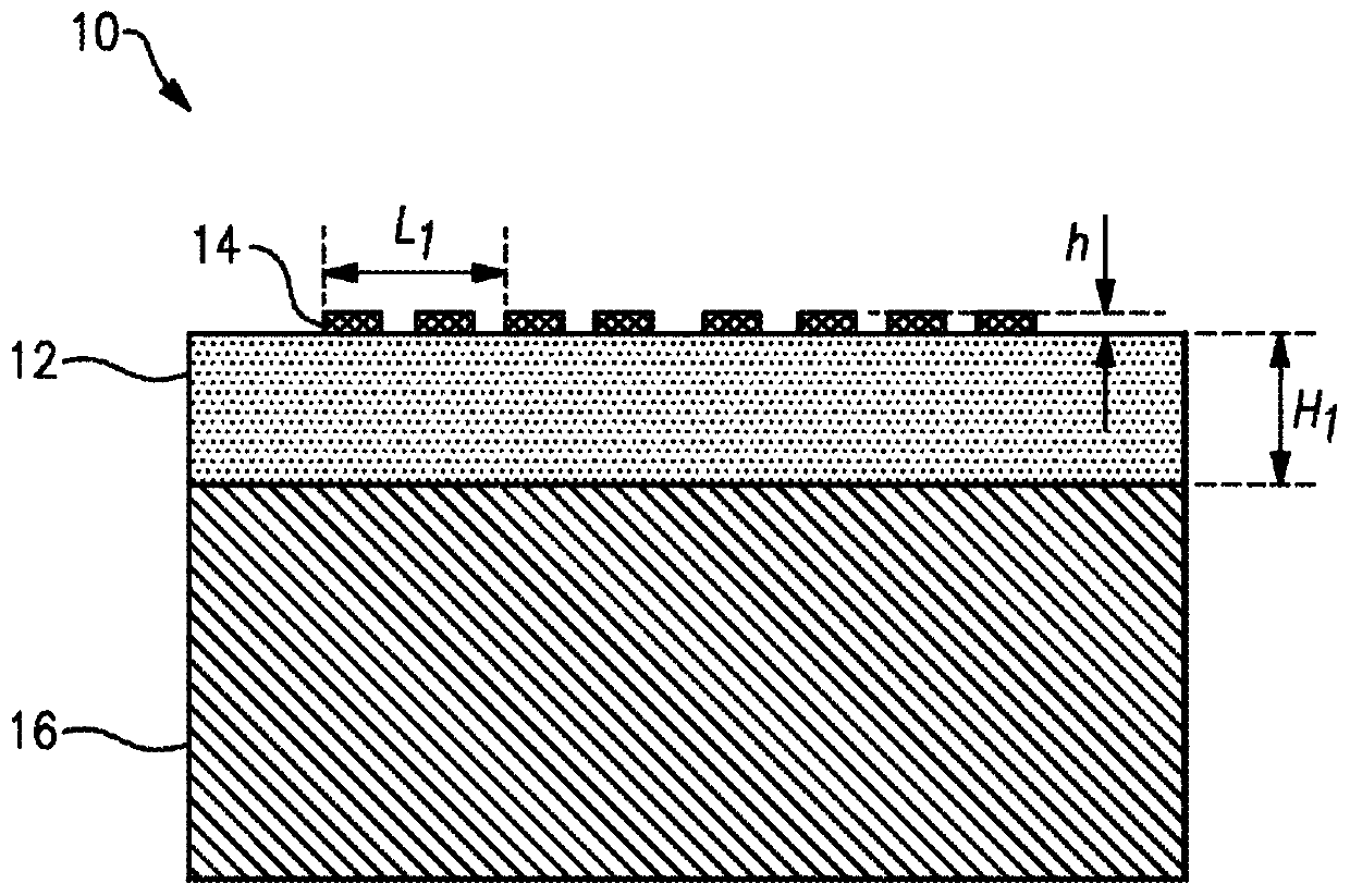
[0127] The following detailed description of certain embodiments presents various descriptions of specific embodiments. However, the invention described herein can be embodied in many different ways, such as as defined and covered by the claims. In this specification, reference is made to the drawings in which like reference numbers may indicate identical or functionally similar elements. It will be understood that elements shown in the figures have not necessarily been drawn to scale. Furthermore, it should be understood that certain embodiments may include more elements than shown in the figures and / or a subset of the elements shown in the figures. Furthermore, some embodiments may combine features from two or more figures in any suitable combination.

[0128] Lithium niobate (LiNbO 3 ) elastic wave devices can have a relatively large electromechanical coupling coefficient (K 2 ). Such devices can operate in leaky surface acoustic wave mode, where horizontal shear (SH) ...


PUM


Abstract

Aspects of the disclosure relate to an elastic wave device. The elastic wave device includes a sub-wavelength thick piezoelectric layer, an interdigital transducer electrode on the piezoelectric layer, and a high velocity layer with a higher bulk velocity than the velocity of an elastic wave. The high velocity layer can inhibit an elastic wave from leaking from the piezoelectric layer at anti-resonance.

Description

[0001] Cross References to Related Applications [0002] This application claims priority to U.S. Provisional Patent Application No. 62 / 410,804, filed October 20, 2016, entitled "ELASTIC WAVE DEVICE," the disclosure of which is incorporated herein by reference. This application claims priority to US Provisional Patent Application No. 62 / 423,705, filed November 17, 2016, entitled "ELASTIC WAVE DEVICE," the disclosure of which is incorporated herein by reference. technical field [0003] The present application relates to an elastic wave device. Background technique [0004] Elastic wave devices can realize surface acoustic wave resonators. A surface acoustic wave resonator may include interdigital transducer electrodes on a piezoelectric substrate. The surface acoustic wave resonator can generate surface acoustic waves on the surface of the piezoelectric layer on which the interdigital transducer electrodes are disposed. Surface acoustic wave resonators can realize surface...

Claims


Application Information

Patent Timeline
Patent Type & Authority Applications(China)
IPC IPC(8): H01L41/107H01L41/187H01L41/083H01L41/047H10N30/40H10N30/50H10N30/853H10N30/87
CPCH03H9/02559H03H9/02574H03H9/02834H03H9/02818H03H9/25H03H9/6483H03H9/6489H03H9/725H10N30/87H10N30/877H10N30/8542H03H9/02015H10N30/706H10N30/40H10N30/50
Inventor 后藤令邹杰中村弘幸C·S·林
Owner SKYWORKS SOLUTIONS INC
Learn More