Built-in permanent magnet synchronous motor and rotor magnetic bridge thereof

A permanent magnet synchronous motor, built-in technology, applied in the direction of magnetic circuit rotating parts, magnetic circuit shape/style/structure, etc., can solve the problem of low output characteristics of the motor, reduce the risk of fracture, reduce the design width, The effect of reducing stress

Inactive Publication Date: 2019-06-14
SHOUGANG ZHIXIN QIAN AN ELECTROMAGNETIC MATERIALS CO LTD +1
View PDF2 Cites 0 Cited by
  • Summary
  • Abstract
  • Description
  • Claims
  • Application Information

AI Technical Summary

Problems solved by technology

[0004] The invention provides a rotor magnetic bridge of a built-in permanent magnet synchronous motor, which solves the technical problem in the prior art that the built-in permanent magnet synchronous motor is limited by the mechanical strength requirements of the magnetic isolation bridge and the output characteristics of the motor are low

Method used


Image

  • Built-in permanent magnet synchronous motor and rotor magnetic bridge thereof
  • Built-in permanent magnet synchronous motor and rotor magnetic bridge thereof
  • Built-in permanent magnet synchronous motor and rotor magnetic bridge thereof

Examples


Embodiment 1

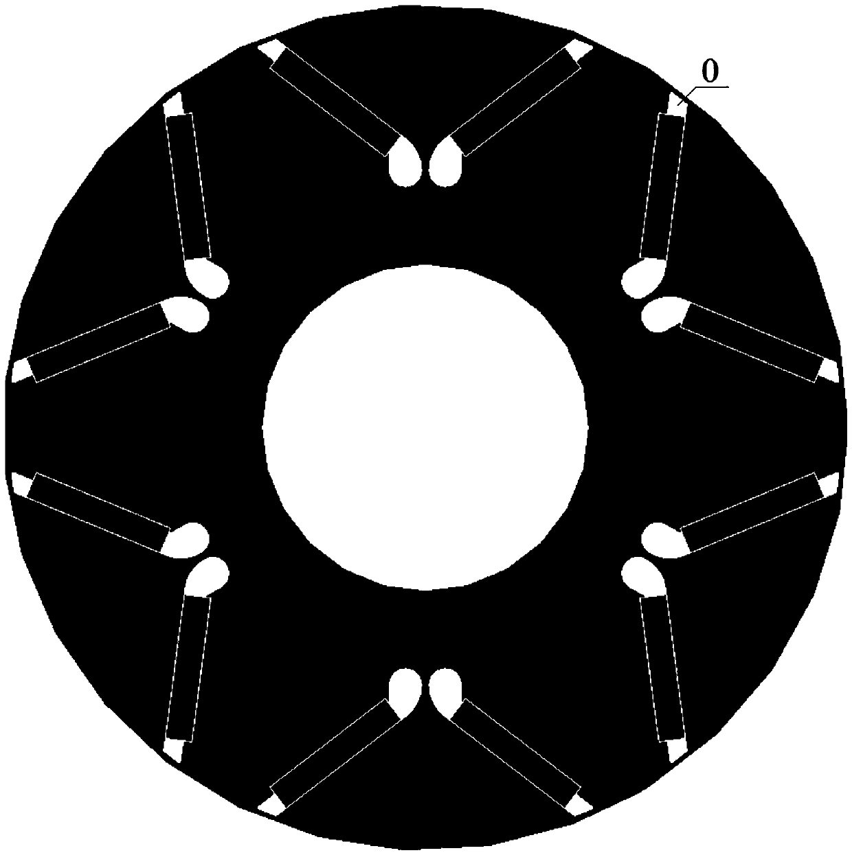
[0027] see figure 2 , the present application provides an embodiment in which the structure of the main body of the magnetic bridge is mostly the same as that of the present application, and the difference is only in the boundary 0 of the outer magnetic bridge of the magnetic bridge main body away from the air gap side, and a performance comparison study is carried out.

[0028] A built-in permanent magnet synchronous motor with a rotor outer diameter of 65 mm and a maximum speed of 20,000 rpm.

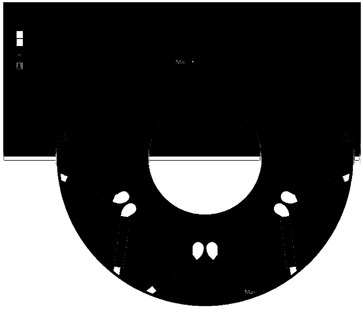
[0029] see figure 2 , image 3 with Figure 5 , in the comparative example, the width of the magnetic bridge is 1.1mm, and the shape is relatively long and narrow. When the speed is 20000rpm, the maximum value of the simulated rotor magnetic bridge stress is 1089MPa; the maximum value of the simulated motor output torque is 259Nm; the average value of the motor efficiency is 96.89%.

[0030] see figure 1 , Figure 4 with Image 6 , the magnetic bridge shape disclosed in this ...

Embodiment 2

[0036] see Figure 7 with Figure 8 , the magnetic isolation bridge solution provided in this embodiment, when the magnetic bridge width is 0.5mm, when the rotating speed is 20000rpm, the maximum value of the simulated rotor magnetic bridge stress is 1081MPa, and the maximum value of the simulated motor output torque is 265Nm; the motor efficiency is average The value is 96.85%.

[0037] The parameters of the two design schemes with different magnetic bridge widths are compared as follows:

[0038] project

comparative example

this application

Compared

in conclusion

Magnetic bridge stress (MPa)

1089

1081

0.7%

The two are basically equivalent

Motor output torque (Nm)

259

265

2.3%

This application has certain advantages

Motor efficiency (%)

96.89

96.85

-0.04%

The two are basically equivalent

[0039] Wherein, the magnetic bridge width of the comparative example is 1.1 mm, and the magnetic ...


PUM


Abstract

The invention belongs to the technical field of motors, and discloses a rotor magnetic bridge of a built-in permanent magnet synchronous motor. The rotor magnetic bridge comprises a magnetic bridge main body, wherein the edge, far from an air gap, of an outer magnetic bridge of the magnetic bridge main body is an arc, one end of the arc is tangent to the edge of a narrow magnetic bridge, and the other end thereof is contacted with the edge of a permanent magnetic bridge. The rotor magnetic bridge can reduce stress of a magnetic isolation bridge under equal width, thereby fully reducing width of the magnetic isolation bridge compared with existing magnetic isolation bridge and enhancing the output characteristic.

Description

technical field [0001] The invention relates to the technical field of motors, in particular to a built-in permanent magnet synchronous motor and a rotor magnetic bridge thereof. Background technique [0002] The rotor structure of the built-in permanent magnet synchronous motor contains a magnetic isolation bridge. The purpose of its setting is to prevent the permanent magnet from being too large in the leakage coefficient and lead to a low utilization rate of the permanent magnet, so as to adopt magnetic isolation measures; the main realization method Yes: Separate the two permanent magnets with a silicon steel sheet, and the silicon steel sheet between the two permanent magnets is called a magnetic isolation bridge. Its function: on the one hand, based on the characteristic that the magnetic density at the magnetic bridge is easily saturated, the leakage flux is reduced, thereby improving the output characteristics of the motor; on the other hand, it is used to connect th...

Claims


Application Information

Patent Timeline
Patent Type & Authority Applications(China)
IPC IPC(8): H02K1/27
Inventor 李广林姜瑞雪安冬洋马琳王付兴刘磊胡志远孙茂林
Owner SHOUGANG ZHIXIN QIAN AN ELECTROMAGNETIC MATERIALS CO LTD
Why Eureka
Try Eureka