Multi-spindle processing center with rotary table

A processing center and multi-spindle technology, which is applied in metal processing, metal processing equipment, metal processing machinery parts, etc., can solve the problems of unfavorable space rational use, excessive occupied area, and large lateral width of multi-spindle processing centers, so as to improve the site Utilization rate, the effect of reducing the width of the overall design

Active Publication Date: 2017-08-11
GUANGZHOU CITY AGILE MFG
View PDF5 Cites 3 Cited by
  • Summary
  • Abstract
  • Description
  • Claims
  • Application Information

AI Technical Summary

Problems solved by technology

As a result, in the design and manufacture process of the multi-spindle machining center, it is necessary to set a longer beam to meet the lateral travel displacement of the multi-spindle box, which will cause the lateral width of the multi-spindle machining center to be too large. Excessive occupation of area is not conducive to the rational use of space

Method used


Image

  • Multi-spindle processing center with rotary table
  • Multi-spindle processing center with rotary table
  • Multi-spindle processing center with rotary table

Examples


Embodiment Construction

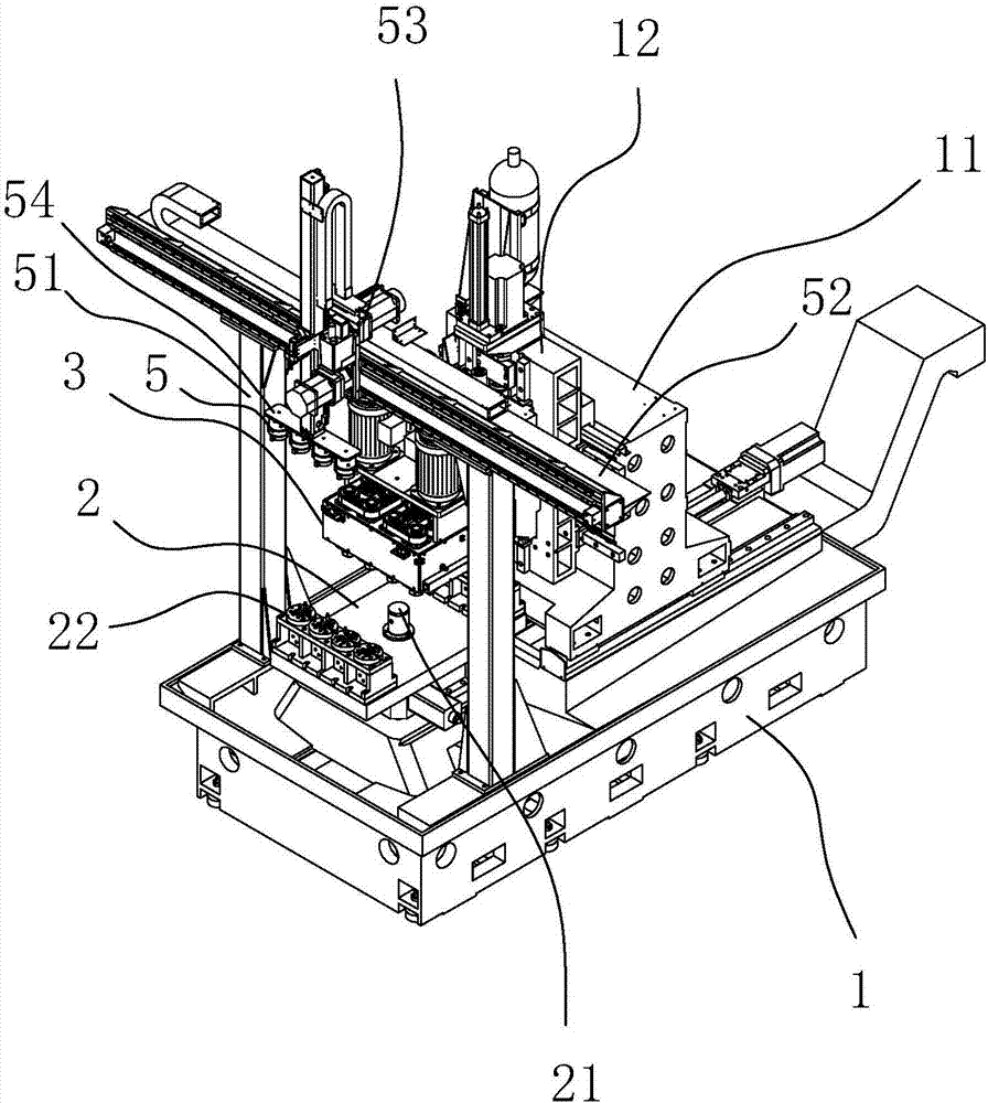
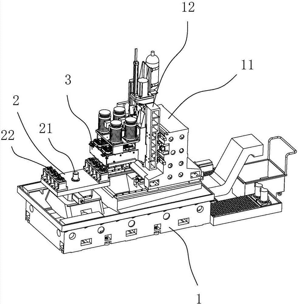
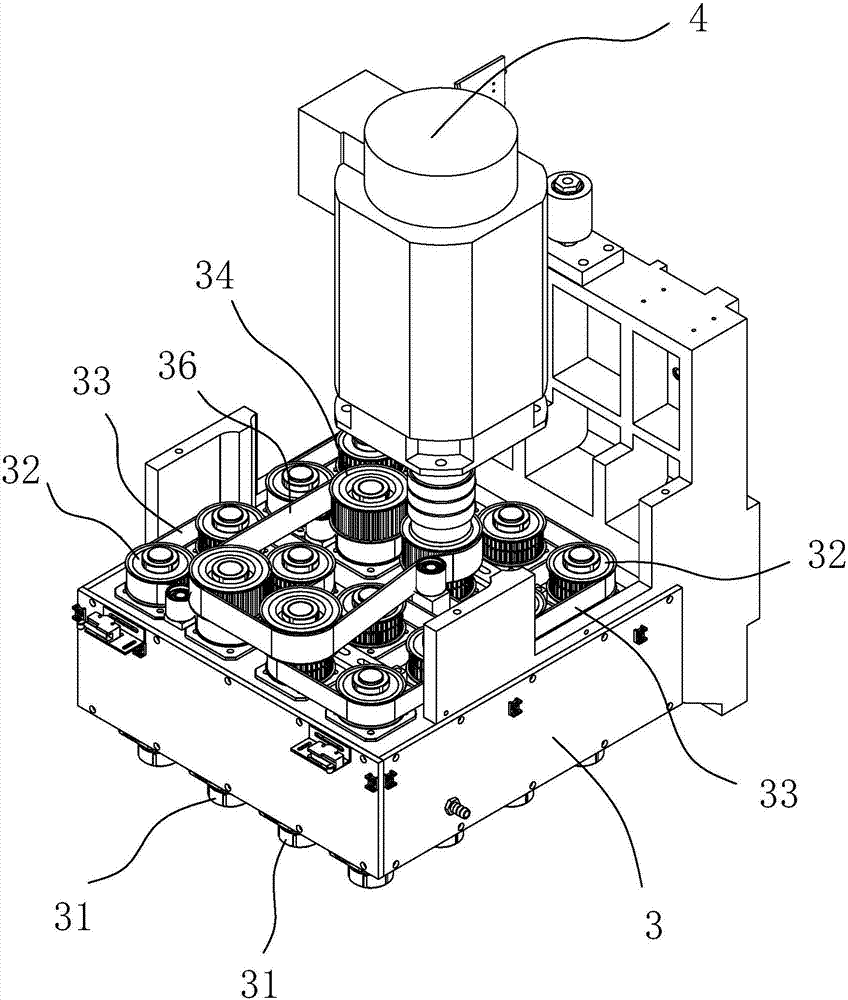
[0021] refer to Figure 1 to Figure 5 , the present invention is a multi-spindle machining center with a turntable, comprising a machine base 1, a machine frame 11 moving along the Y direction on the machine base 1, a headstock seat 12 installed on the top of the machine frame 11, and a headstock seat that can be mounted on the machine tool base 1. 12, the multi-spindle box 3 moving along the Z direction, the machine tool base 1 is located on the side where the multi-spindle box 3 is located is also provided with a turntable 2 that can rotate around the Z axis, and the inner and outer sides of the turntable 2 along the Y direction are respectively provided with straight lines. Several workpiece fixtures 22 arranged at intervals, a plurality of machining spindles 31 arranged in a matrix are arranged in the multi-spindle box 3, and the number and spacing of each row of machining spindles 31 in the multi-spindle box 3 are related to the workpiece fixtures arranged in rows. 22 cor...


PUM


Abstract

The invention discloses a multi-spindle processing center with a rotary table. The multi-spindle processing center comprises a machine tool base, a machine tool rack which moves in the Y direction on the machine tool base, a spindle box base mounted on the upper part of the machine tool rack and a multi-spindle box which can move in the Z direction on the spindle box base, wherein the rotary table which can rotate around a Z axis is further arranged on the side, at which the multi-spindle box is located, of the machine tool base; a plurality of workpiece clamps which are linearly arranged in a spaced mode are separately arranged at the inner side and the outer side in the Y direction of the rotary table; a plurality of processing spindles which are arranged in the form of a matrix are arranged in the multi-spindle box; and number and spacing of each row of processing spindles in the multi-spindle box correspond to workpiece clamps which are arranged in rows. The multi-spindle processing center with the rotary table disclosed by the invention performs displacement control in a multi-station processing process of the multi-spindle box by moving the machine tool rack in the Y direction and moving the multi-spindle box in the Z direction; stroke displacement in a station transfer process is movement in a plane perpendicular to the X direction, so that integral design width of the multi-spindle processing center is effectively reduced; and in a site space with limited width, work of more multi-spindle processing centers can be convenient, so that the site utilization rate is favorably increased. The multi-spindle processing center is used for the machine tool processing field.

Description

technical field [0001] The invention relates to the field of machine tool processing, in particular to a multi-spindle machining center with a turntable. Background technique [0002] In the existing multi-spindle machining center, the parts arranged in rows on the turntable are processed through the multi-spindle box. After one process is completed, the multi-spindle box is moved as a whole, and the next process is processed through another row of spindles on the multi-spindle box. , in this process, the existing multi-spindle machining center adjusts the station by moving the multi-spindle box laterally. As a result, in the design and manufacture process of the multi-spindle machining center, it is necessary to set a longer beam to meet the lateral travel displacement of the multi-spindle box, which will cause the lateral width of the multi-spindle machining center to be too large. Excessive occupation of the area is not conducive to the rational use of space. Contents ...

Claims


Application Information

Patent Timeline
Patent Type & Authority Applications(China)
IPC IPC(8): B23Q39/02B23Q5/10
CPCB23Q5/10B23Q39/021B23Q2039/006
Inventor 赵虎谢政平梁羡升郭炜文罗俊杰
Owner GUANGZHOU CITY AGILE MFG
Why Eureka
Try Eureka