
Servo motor

A servo motor and motor stator technology, applied in the field of servo motors, can solve the problems of dislocation movement of the rotor rotation direction, affecting the performance of equipment, low power density, etc., to prevent dislocation movement, improve connection reliability, and reduce the effect of length.

Pending Publication Date: 2019-06-14
DORNA TECH
View PDF0 Cites 0 Cited by
  • Summary
  • Abstract
  • Description
  • Claims
  • Application Information

AI Technical Summary

Problems solved by technology

[0003] 1) The shape is long and the power density is low, which affects the installation and application of terminal smart devices and the performance of the devices, especially the application of multi-joint robots
[0004] 2) Servo motors have high requirements on the reliability of the rotor in some occasions of rapid acceleration and deceleration and repeated forward and reverse switching. The existing shaft and rotor core are connected through simple interference. Long-term high-intensity work will cause material to appear. Creep, there is a certain probability of dislocation movement of the rotor rotation direction
But this is a contradiction with the iron core stamping process. The die stamping fillet needs to be kept above 0.2, and the larger the fillet, the sharper corner of the die is not easy to break, and the life of the die will be longer

Method used


Image

  • Servo motor
  • Servo motor
  • Servo motor

Examples


Embodiment Construction

[0039] In order to make the technical means, creative features, goals and effects achieved by the present invention easy to understand, the present invention will be further described below in conjunction with specific embodiments.

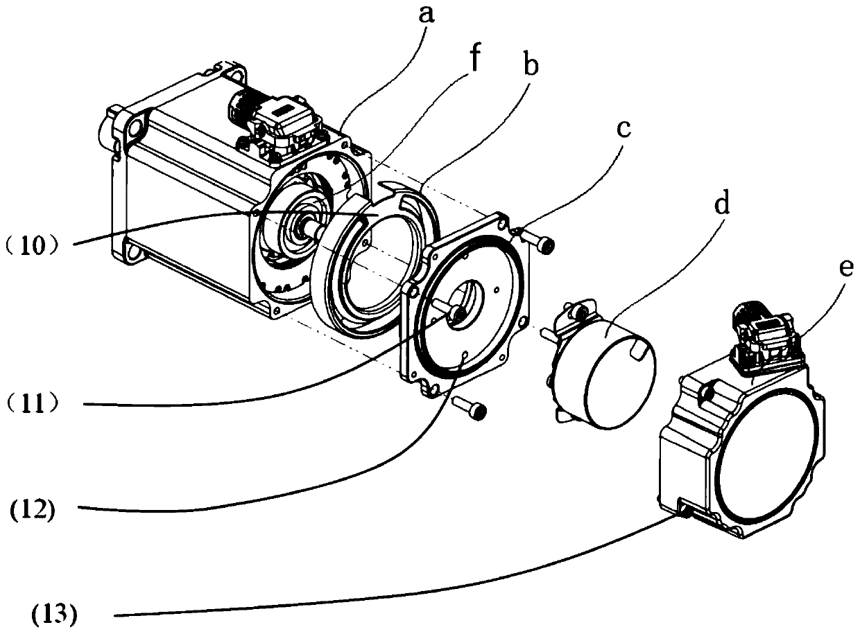
[0040] see Figure 1-Figure 13 , a servo motor according to the present invention, comprising a motor stator (a), an insulating end portion (b), an end cover (c), a rear cover (d), an encoder (e) and a motor rotor (f);

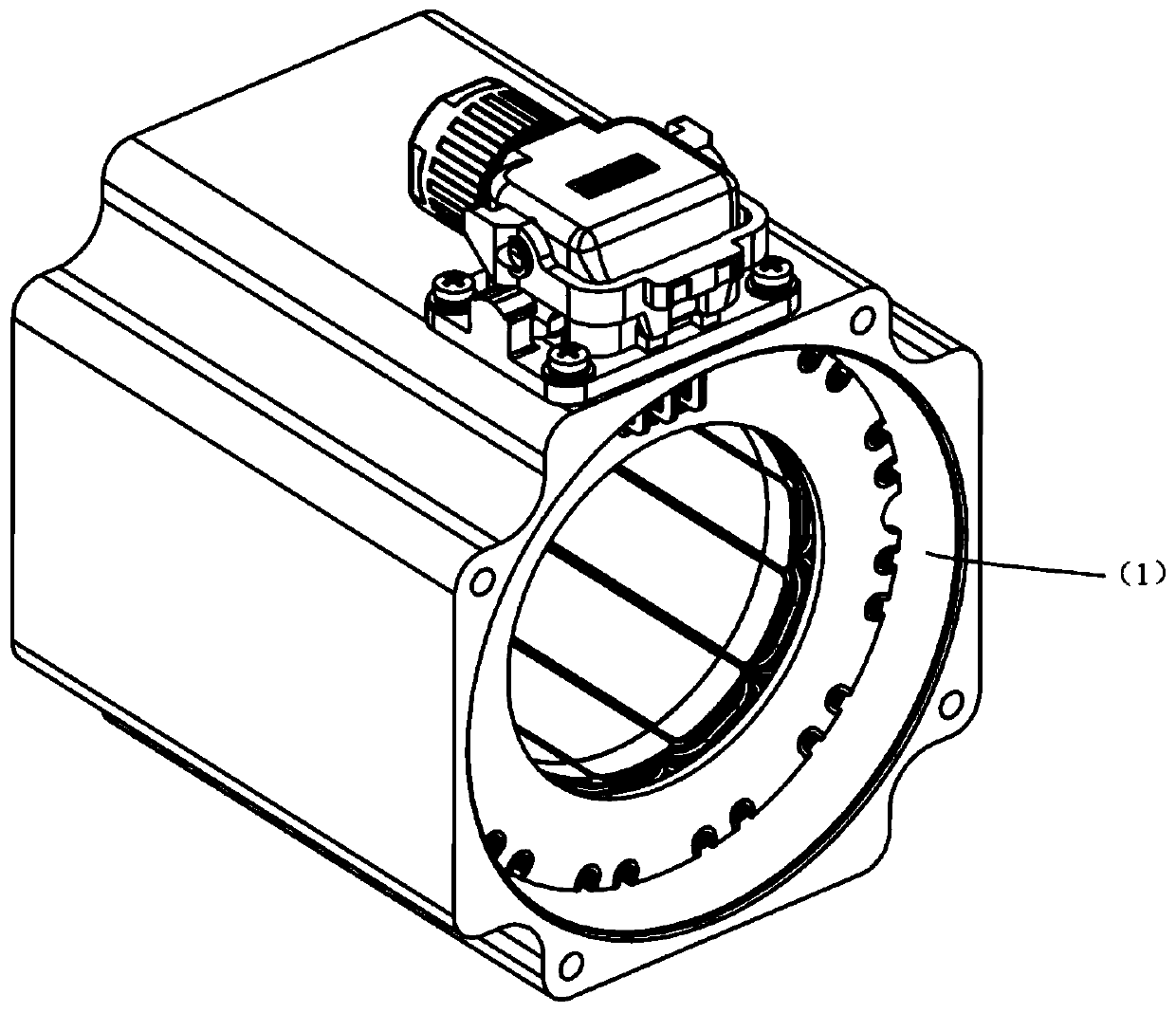
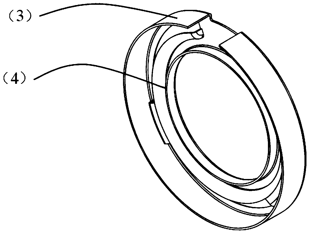
[0041] The opening end of the motor stator (a) is provided with a first notch (1), and is connected to the insulating end (b) through the first notch (1), and the inner end surface of the insulating end (b) Set as the positioning end face (4) connected with the motor stator (a), the positioning end face (4) is provided with the second seam (3) matching with the first seam (1), and the insulating end (b) is close to The PCB (2) inside the motor stator (a), and the inside of the motor stator (a) fixes the insulating end (b) by pott...


PUM


Abstract

The invention discloses a servo motor connecting structure for shortening length, which comprises a motor stator, an insulating end part, an end cover, a rear cover, an encoder and a motor rotor. Themotor stator is provided with a first spigot, the insulating end part is connected with the motor stator through a second spigot, and the insulating end part is fixed inside the motor stator through encapsulating epoxy resin; one surface of the insulating end part is a flange surface, a through hole is formed in the flange surface, the other surface of the insulating end part is a concave edge surface, and a first screw hole is formed in the concave edge surface; the end cover passes through the through hole via the first screw and is fixedly connected with the motor stator; the flange surfaceand the connecting end surface are both cambered surfaces protruding towards the motor stator, and the gap between the two cambered surfaces is 0.5 mm; a plurality of second screw holes are formed inthe concave edge surface of the insulating end part, the encoder is arranged in the concave edge surface of the insulating end part, and the end surface of the encoder is retracted into the concave edge surface; and a rear cover hole is fixedly connected with the concave edge surface of the insulating end part to form a sealing cavity, and the encoder is wrapped in the sealing cavity.

Description

technical field [0001] The present invention relates to the field of servo motors, in particular to a servo motor. Background technique [0002] Servo motors are the execution layer of industrial control and the core components of intelligent manufacturing. At present, there are many difficulties in domestic servo motors that have not been resolved. For example: [0003] 1) The shape is long and the power density is low, which affects the installation and application of terminal smart devices and the performance of the devices, especially the application of multi-joint robots. [0004] 2) Servo motors have high requirements on the reliability of the rotor in some occasions of rapid acceleration and deceleration and repeated forward and reverse switching. The existing shaft and rotor core are connected through simple interference. Long-term high-intensity work will cause material to appear. Creep, there is a certain probability that the rotor rotates in the wrong direction ...

Claims


Application Information

Patent Timeline
Patent Type & Authority Applications(China)
IPC IPC(8): H02K1/12H02K1/27H02K5/04
Inventor 齐剑
Owner DORNA TECH
Learn More