
A portable detector for AC charging pile

An AC charging pile and detector technology, which is applied to the parts, instruments, measuring electricity and other directions of electrical measuring instruments, can solve the damage to the electrical components of the AC charging pile detector body, the deposition of more dust on the display screen, and the inability to reduce the damage. Vibration and other problems, to avoid debugging the accurate installation position, reduce the vibration effect, and save time.

Active Publication Date: 2021-04-27
ANHUI NENGTONG NEW ENERGY TECH CO LTD
View PDF10 Cites 1 Cited by
  • Summary
  • Abstract
  • Description
  • Claims
  • Application Information

AI Technical Summary

Problems solved by technology

[0003] In order to facilitate operation and portability, the traditional AC charging pile detector puts the main body of the AC charging pile detector in a portable box and seals it through the box cover, but the existing storage box has the following disadvantages: (1) When the AC charging pile detector After the charging pile detector body is placed in the box and the box cover is covered, there will be a large gap between the AC charging pile detector body and the box cover. Such a long-term storage will cause more dust to accumulate on the display screen. This is not conducive to the long-term use of the display screen; (2) due to the existence of gaps, when there are solid particles, when vibration occurs, it is easy for the solid particles to cause impact on the display screen, thereby causing damage to the display screen; (3) At the same time, the shock absorption protection measures in the box are relatively simple. When vibration occurs, it cannot play a good shock absorption effect, which will easily damage the electrical components inside the body of the AC charging pile detector.

Method used


Image

  • A portable detector for AC charging pile
  • A portable detector for AC charging pile
  • A portable detector for AC charging pile

Examples


Embodiment Construction

[0027] The following will clearly and completely describe the technical solutions in the embodiments of the present invention with reference to the accompanying drawings in the embodiments of the present invention. Obviously, the described embodiments are only some, not all, embodiments of the present invention. Based on the embodiments of the present invention, all other embodiments obtained by those of ordinary skill in the art without creative efforts shall fall within the protection scope of the present invention.

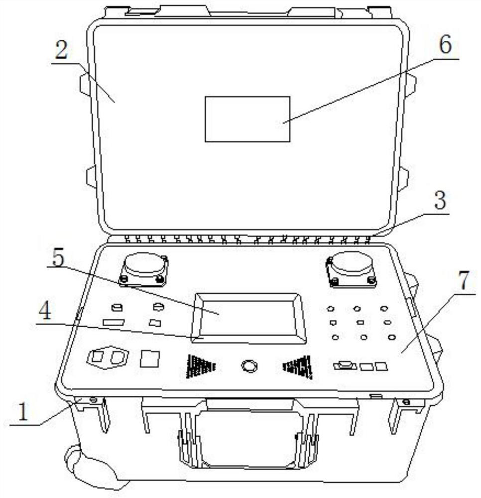
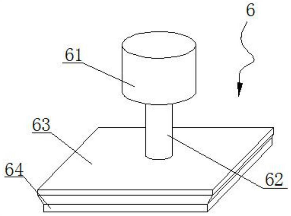
[0028] Please also refer to Figures 1 to 7 , a portable tester for an AC charging pile provided in an embodiment of the present invention, comprising a box body 1, on which a box cover 2 is hinged through a connector 3, a tester body 7 is arranged inside the box body 1, and the tester body 7 is provided with a groove 4, a display screen 5 is arranged in the groove 4, a protective assembly 6 matching the display screen 5 is fixedly connected to the case cover 2...


PUM


Abstract

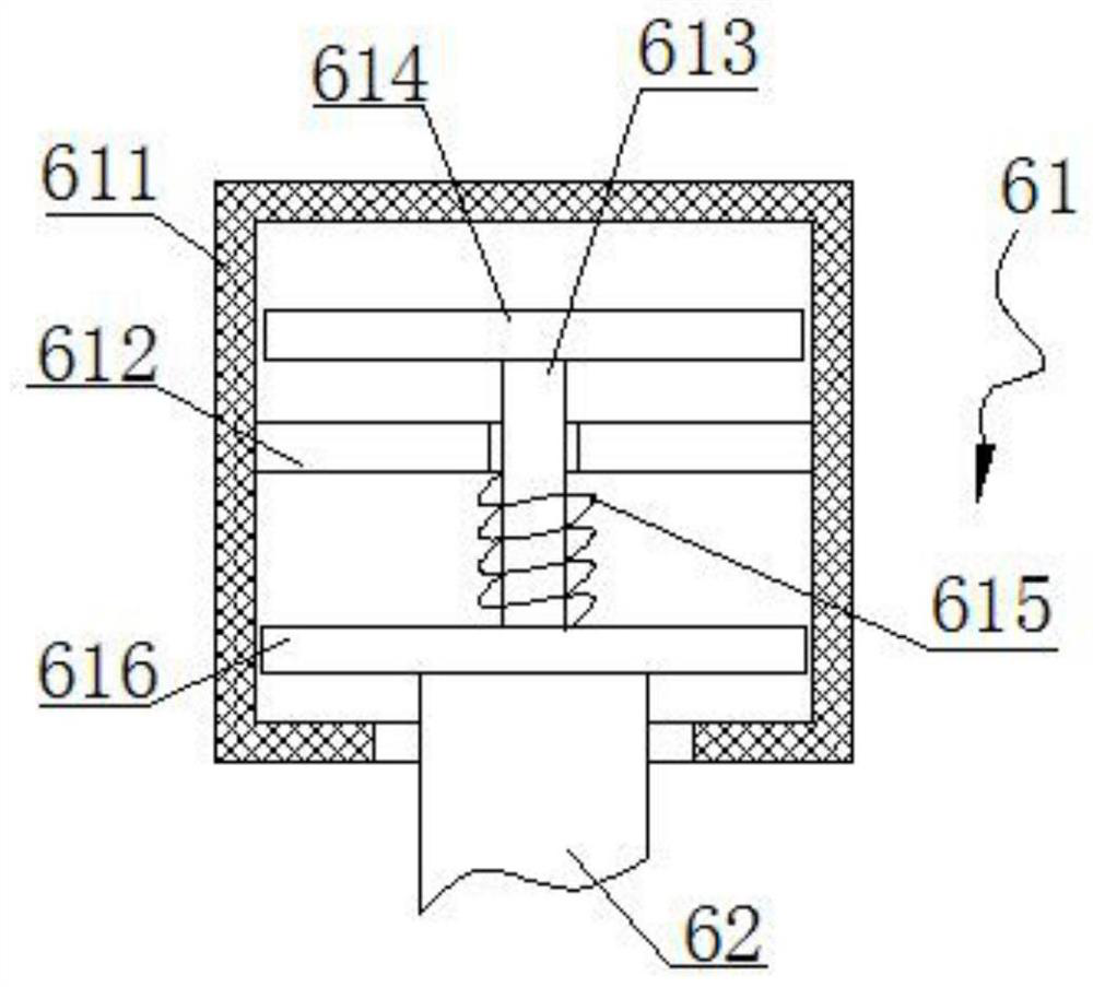
The invention discloses a portable detector for an AC charging pile, which comprises a box body, a box cover is hinged on the box body through a connecting piece, a detector body is arranged in the box body, a groove is opened on the detector body, and a groove is arranged in the groove The display screen is fixedly connected with a protective assembly matching the display screen, and the inner bottom wall of the box is fixedly connected with a shock absorber. In the present invention, by adding a combined structure of the protective assembly and the shock absorber, the protective assembly The setting, when the box cover is closed, will make the protective component match the groove and the display screen, so that it can not only play a dust-proof effect, but also play a role in protecting the display screen under the action of the protective component. The setting of the shock absorbing device can play a very good shock absorbing effect, so that when the vibration occurs, the effect of the shock absorbing device will reduce the vibration effect, and avoid excessive vibration of the electrical components inside the detector body, thereby causing damage.

Description

technical field [0001] The invention relates to the technical field of AC charging pile equipment, in particular to a portable detector for AC charging piles. Background technique [0002] The charging pile detector is a detector that displays voltage and current values. Main functions: According to the testing requirements of performance parameters, the corresponding power can be set through the operation panel, and the discharge power can be set in any combination. Three-phase independent control; the whole machine adopts electronic circuit control, with automatic overheating protection function: when overheating occurs due to special reasons, the load can be automatically cut off. Display voltage, current value, power factor of each phase, frequency, active power of each phase, etc., and realize data storage function through PC. The power input adopts segmented method. The load works in the way of energy consumption, and the heat dissipation adopts the forced air cooli...

Claims


Application Information

Patent Timeline
Patent Type & Authority Patents(China)
IPC IPC(8): G01R31/00G01R1/02
Inventor 陶旭何仕玉张文飞
Owner ANHUI NENGTONG NEW ENERGY TECH CO LTD
Learn More