Automatic tap density measuring device
A technology of tap density and measuring device, which is applied in the direction of measuring device, specific gravity measurement, instrument, etc., can solve the problems of non-adjustable, limited application range, uneven surface of powder, etc., and achieve the effect of improving measurement accuracy and expanding application range
- Summary
- Abstract
- Description
- Claims
- Application Information
AI Technical Summary
Problems solved by technology
Method used
Image


Examples
Embodiment 1
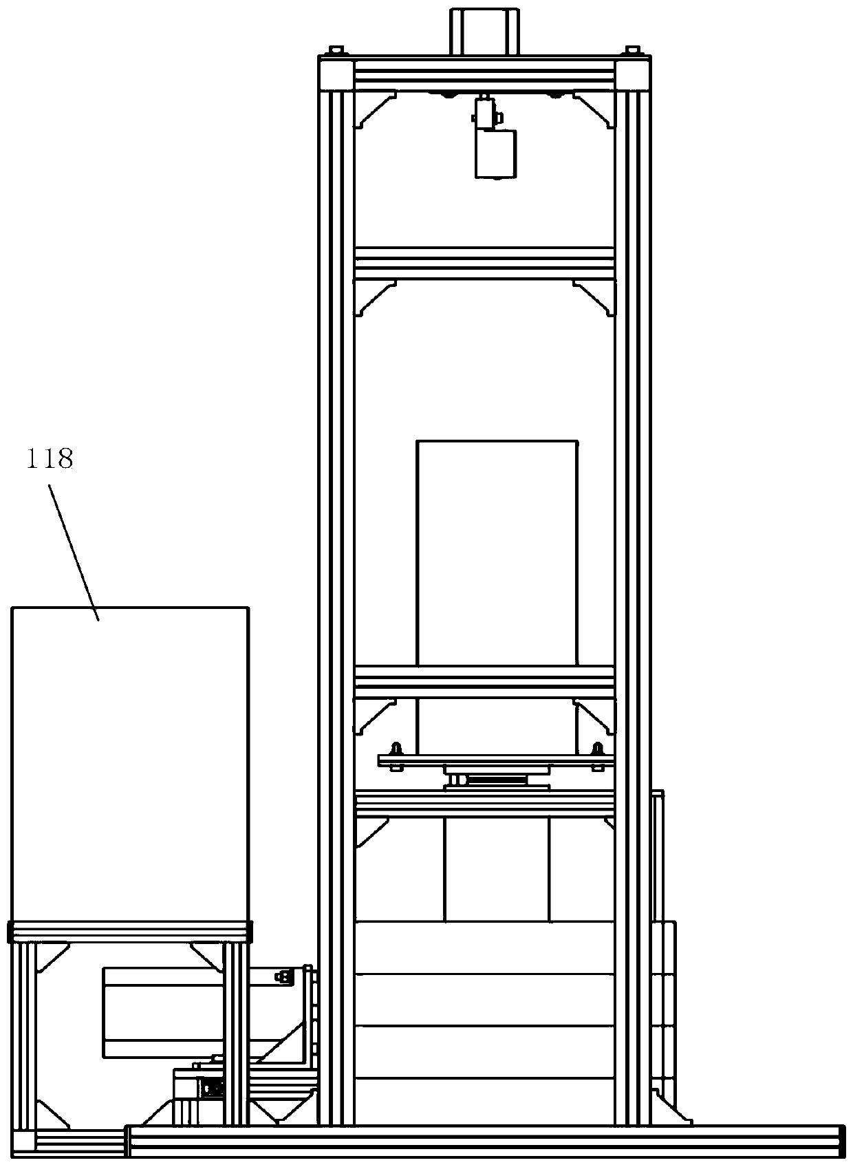
[0042] Such as figure 1 , 2 As shown, an automatic tap density measuring device includes: a vibration mechanism, a distance measurement scanning device and a control system; the container is installed on the vibration mechanism; the vibration mechanism applies vertical mechanical vibration to the powder particles in the container; the distance measurement scanning The device is installed above the vibrating mechanism; the ranging scanning device performs ranging scanning on the contour of the powder accumulation surface in the container; the control system automatically controls and collects data on the vibrating mechanism and the ranging scanning device.
[0043] In order to further optimize the above-mentioned technical scheme, such as image 3 , 6 As shown, the vibration mechanism includes a container holder 11, a vibrating rod 12, a follower 13, a bearing follower 14, a vibration swing rod 15 and a mixing servo motor 16; the container holder 11 is placed with a container...
Embodiment 2
[0056] On the basis of Example 1, replace the bearing follower 14 with the follower 13, and open a waist-shaped hole on the bearing follower 14, the follower 13 is installed in the waist-shaped hole, and the vibration pendulum 15 swings back and forth , driving the vibrating rod 12 to slide up and down continuously to realize continuous vibration, and other contents are the same as those in Embodiment 1, and will not be repeated here.
[0057] Further, a spring 121 is provided between the container fixing base 11 and the anvil 112 during continuous vibration.
Embodiment 3
[0059] On the basis of Embodiment 1, the centerline of the output shaft of the stepper motor 22 is parallel to the centerline of the container, and the use of the circular scanning mode means that the centerline of the output shaft of the stepper motor 22 coincides with the centerline of the container, and the scanning swing arm 21 drives The laser ranging sensor 24 moves at a uniform speed along the circumference, and the laser ranging sensor 24 collects powder surface profile data on the circular trajectory;
[0060] In another embodiment, adopting the arc scanning mode means that the stepper motor 22 drives the laser distance measuring sensor 24 to reciprocate at a uniform speed along the arc, and the arc motion track passes through the center line of the container, and the laser distance measuring sensor 24 collects data in the arc. Powder surface profile data on line trajectories.
[0061] Such as Figure 5 As shown, the output shaft of the hybrid servo motor transmits p...
PUM
| Property | Measurement | Unit |
|---|---|---|
| The inside diameter of | aaaaa | aaaaa |
| Depth | aaaaa | aaaaa |
Abstract
Description
Claims
Application Information
 - Generate Ideas
- Intellectual Property
- Life Sciences
- Materials
- Tech Scout
- Unparalleled Data Quality
- Higher Quality Content
- 60% Fewer Hallucinations
Browse by: Latest US Patents, China's latest patents, Technical Efficacy Thesaurus, Application Domain, Technology Topic, Popular Technical Reports.
© 2025 PatSnap. All rights reserved.Legal|Privacy policy|Modern Slavery Act Transparency Statement|Sitemap|About US| Contact US: help@patsnap.com